MX2010 Cooling System Description
The cooling system consists of the following components:
Fan tray—MX2000-FANTRAY
Lower fan tray air filter—MX2010-FLTR-KIT-S
Air baffle—MX2000-UPR-BAFFLE
The cooling system components work together to keep all router components within the acceptable temperature range. The router has four fan trays, two trays located at the top, and two trays located at the bottom of the router that install horizontally. Each fan tray contains six fans and are 172 mm in diameter. The fan trays are interchangeable and are hot-insertable and hot-removable.
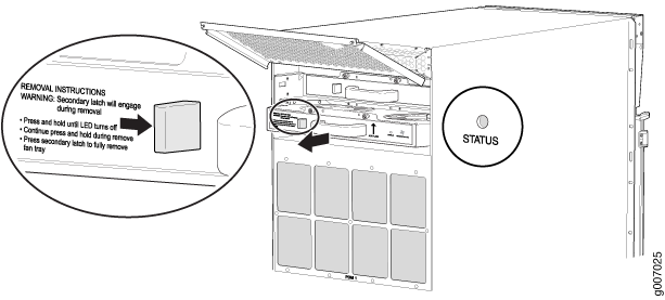
Each fan tray has a double safety latch, so the fan tray cannot be removed in one swift motion (see Figure 1). To remove the fan tray, press and hold the latch until LED turns off. The secondary latch will engage during removal. Press the secondary latch to fully remove the fan tray.

Before removing a fan tray, make sure the fan blades have stopped completely.
The host subsystem monitors the temperature of the router components. When the router is operating normally, the fans function at lower than full speed. If a fan fails or the ambient temperature rises above a threshold, the speed of the remaining fans is automatically adjusted to keep the temperature within the acceptable range (see Figure 2 and Figure 3). The lower fan tray filter is shown in Figure 4.

The MX2010 router provides a two-stage front-to-back cooling system. Air is pushed into the bottom inlet and up through the lower fan tray, and exits through the opening between the backplanes in the center of the chassis. This cools the bottom MPCs, and half of each SFB and CB-RE. Air is pulled through the SFBs and all the CB-REs in the center of the chassis and is exhausted out the upper rear of the system.
The CB-REs and SFBs are equipped with an air divider to deflect the exhaust air for the bottom half of the system out and direct the air for the top half of the system out.

1 — Safety double latch system | 2 — STATUS LED |
Before removing a fan tray, make sure that the fan blades have stopped completely.
The fan trays use a double latch safety mechanism. Press and hold the latch until the STATUS LED turns off. Continue to press and hold the latch while removing the fan trays.

The air baffle is an optional component that can be purchased from Juniper Networks.
When installed over the upper fan tray access door, the air baffle dissipates exhausted air away from the router.
