ON THIS PAGE
Fast Track to Rack Installation and Power
This procedure guides you through the simplest steps for the most common installation to mount your MX2010 router in a rack and connect it to power.
Install the MX2010 in a Rack
You can mount an MX2010 Universal Routing Platform in an open-frame rack, a four-post rack, or a cabinet. In this section, we'll walk you through the steps to install an MX2010 router and connect it to power.
A fully configured router can weigh up to 985 lb (446.79 kg).
Because of the router's size and weight, you can install the router using a pallet jack with a pallet jack attachment, or the router transport kit. We recommend that you use the router transport kit to install the router.
You must install the router into a rack or cabinet that is secured to the building structure in a restricted-access location. You must also ensure that the chassis is always grounded properly.
Before you install, review the following:
Mount the Router
To mount the MX2010 router on a four-post rack using a router transport kit (model number MX2K-TRNSPRT-KIT):
To install the router in a four-post rack, you must install a mounting self. Slide the large shelf between the rack rails, resting the bottom of the shelf on the rack supports. The large shelf installs on the rear rack rails, extending toward the front of the rack.
Note:There must be a minimum of 34-U unobstructed front-to-back usable rack space when installing the MX2010 router into a four-post rack.
Partially insert screws into the open holes in the rear flanges of the four-post mounting shelf.
Note:Depending on the type of rack you have, cage nuts might be required.
Figure 1: Mounting Hardware for a Four-Post Rack or Cabinet
On the front of each front rack rail, partially insert a mounting screw into the holes in each ear of the four-post mounting shelf.
Tighten all the screws completely.
Because of the router's size and weight, you must first remove the components from the chassis before installation.
Figure 2: Components to Remove from the Front of the MX2010 Router
Table 1: Components to Remove from the Front of the MX2010 Router Component No.
Component Description
Slots
Number of FRUs
1
Craft interface
–
1
2
Switch Fabric Boards (SFBs)
0 through 7
8
3
Control Board and Routing Engine (CB-RE)
0 and 1
2
4
MPCs with ADCs and MICs
0 through 9
10
Figure 3: Components to Remove from the Rear of an AC-Powered MX2010 Router
Table 2: Components to Remove from the Rear of an AC-Powered MX2010 Router Component No.
Component Description
Slots
Number of FRUs
1
Upper fan trays (two)
Fan tray 2 and fan tray 3 (behind cage door)
2
2
AC PDM—Three-phase delta or wye
PDM1/Input1
1
3
AC PSM
0 through 8
9
4
PSM air filter
–
1
5
AC PDM—Three-Phase delta or wye
PDM0/Input0
1
6
Fan tray air filter
–
1
7
Lower fan trays (two)
Fan tray 0 and fan tray 1 (behind access door)
2
To remove the components from the router:
Slide each component out of the chassis evenly so that it does not become stuck or damaged.
Label each component as you remove it so you can reinstall it in the correct location.
Immediately store each removed component in an electrostatic bag.
Lay each component on a flat surface. Do not stack the removed components.
To remove the upper and lower fan tray:
Note:The fan trays are interchangeable and are hot-insertable and hot-removable.
Attach an electrostatic discharge (ESD) grounding strap to your bare wrist, and connect the strap to an approved site ESD grounding point. Refer the instructions for your site.
Loosen the two captive screws on each side of the fan tray access panel and open.
Loosen the two captive screws on the fan tray faceplate.
Press and hold the latch while simultaneously pulling the fan tray out approximately 1 to 3 in. Place one hand under the fan tray for support, while pulling the fan tray completely out of the router.
Note:The double latch system is a safety mechanism, so you cannot pull the fan tray out in one motion.
Place each component on an antistatic mat resting on a stable, flat surface. Do not stack fan trays on top of another after you remove them.
Figure 4: Removing Upper Fan Trays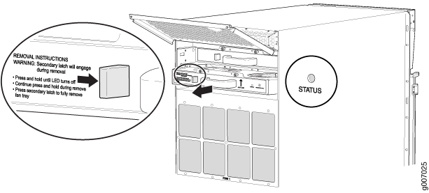 Figure 5: Removing Lower Fan Trays
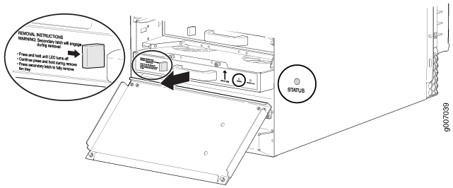 Note:
Note:For complete instructions on removing router components, see Removing Components from the MX2010 Router Chassis Before Installing It in a Rack.
Remove the router transport kit from the shipping crate (see Unpacking the MX2010 Router Transport Kit).
Remove the winch strap plate that is secured to the winch mount by using a 9/16-in. (14 mm) socket wrench, and set the plate aside.
Using a number 3 Phillips screwdriver, loosen the captive screws that secure the winch mount to the router transport kit, and set the mount aside.
Using a number 3 Phillips screwdriver, loosen the captive screws that secure the router transport mounting plate and wheel assembly (left and right) to the router transport platform, and set them aside.
Figure 6: Preparing the Router Transport Kit for Installation
Remove the four shipping brackets that secure the router to the shipping crate platform by using a 9/16-in. (14 mm) socket wrench and a number 2 Phillips screwdriver, and set the brackets aside.
Align the left router transport mounting plate and wheel assembly (indicated by left arrow shown on the assembly) with the holes on the left side of the chassis.
Figure 7: Installing the Router Transport Kit onto the MX2010 Router
Using a number 3 Phillips screwdriver, tighten the captive screws to secure the router transport mounting plate and wheel assembly to the chassis.
Align the right router transport mounting plate and wheel assembly (indicated by right arrow shown on the assembly) with the holes on the right side of the chassis (see Figure 7).
Using a number 3 Phillips screwdriver, tighten the captive screws to secure the router transport mounting plate and wheel assembly to the chassis.
Once you have installed the router transport kit onto the router, you can now secure the router to the transport platform. Using the shipping crate door as a ramp, secure the door to the crate platform by using the two metal latches.
Figure 8: Securing the Crate Door to the Shipping Crate Platform
Using a two-person team on either side of the chassis, turn the handles on the router transport 4–5 times until the chassis is raised approximately 1 in. (2.54 cm), making sure that the chassis is level.
Note:The router transport kit is equipped with four T-shaped levels on top of each of the four router transport mounting brackets. Make sure the bubbles within the T-shaped levels are between the lines, indicating the chassis is level.
CAUTION:Do not raise the chassis above 1 in. (2.54 cm). This will ensure the router will not tilt when transporting, which can result in injury or damage to the router.
Turn the four wheels on the router transport kit toward the rear of the chassis.
Grasping the handles on the shipping covers, carefully guide the chassis down the crate ramp to the rack location.
Warning:Do not push or pull the router fast while transporting. Using excessive speed can cause the wheels to turn abruptly and tilt the router over.
CAUTION:Do not lift the router by using the handles on the shipping covers. Use these handles only to help position the router.
Position the router transport platform directly under the router, aligning the router transport platform with the bottom of the chassis by adjusting the four leveling mounts.
Secure the router transport platform to the router transport mounting plates by using the four latch locks.
Figure 9: Securing the Router Transport Platform
Once the router is secured to the transport platform, you can now install the router in a four-post rack. Install the winch strap plate to the rear of the router by tightening the four captive screws.
Note:Four people are needed to install the router into a rack.
CAUTION:Before front-mounting the router in a rack, have a qualified technician verify that the rack is strong enough to support the router's weight and is adequately supported at the installation site.
Figure 10: Installing Winch Strap Plate (Four-Post Rack)
Using a four-person team, transport the router to the rack installation location and center it in front of the mounting shelf.
Install the winch mount bracket to the rear rack rails by using the six captive screws, and tighten the screws.
Figure 11: Installing Winch Mount Bracket to Rack Rails
Adjust the height of the router by turning the handles clockwise until the router transport platform is aligned with the surface of the mounting shelf and slightly higher than the mounting shelf.
Note:Make sure the bubbles within the T-shaped levels are between the lines, indicating that the router is level.
Figure 12: Aligning the MX2010 Router with Rack Mounting Shelf
Adjust the four leveling mounts on the router transport platform until all four leveling mounts rest firmly on the ground (see Figure 12).
Unlock the four toggle latches that secure the router transport platform to the router transport mounting plate and wheel assembly.
Lift the wheels up by turning the handles counterclockwise so that the weight of the router is on the router transport platform.
Using a number 3 Phillips screwdriver, loosen the captive screws that secure the router transport mounting plates and wheel assembly to the chassis, and set them aside.
Figure 13: Removing Router Transport Mounting Plate and Wheel Assembly
Attach the winch strap to the winch strap plate at the rear of the router.
Figure 14: Attaching Winch Strap to Winch Strap Plate
Attach a 1-1/8 in. (28.57 mm) torque-controlled driver or socket wrench to the winch mechanism and turn clockwise to start pulling the chassis into the rack.
Figure 15: Pulling the MX2010 into the Rack Note:
Note:A four-person team is needed to carefully guide the router into the rack while operating the winch.
Note:If the router is not pulled all the way into the rack by the winch mechanism, grasp the handles on the shipping covers and carefully slide the router onto the mounting shelf until the front-mounting flanges contact the rack rails. You must remove the winch bracket to perform this procedure.
Note:There must be a minimum of 45-U of usable rack space when installing the MX2010 into a 45-U rack.
Remove the router transport platform, and set the platform aside.
Remove the winch mount and winch strap plate, and set them aside.
Insert twelve mounting screws (six on each side) into the mounting holes to secure the router to the rack.
Visually inspect the alignment of the router. To verify that the router is installed properly in the rack, see that all the mounting screws on one side of the rack are aligned with the mounting screws on the opposite side and the router is level.
Reassemble the router transport kit, and set it aside.
Reinstall the components in the router:
Take each component out of its electrostatic bag, and identify the slot on the component where it will be connected.
Slide each component into the chassis evenly so that it does not become stuck or damaged.
Tighten the captive screws, and secure all levers for each component.
Note:Make sure that all empty slots are covered with a blank panel before operating the router.
Connect to Power
The MX2010 router supports -48 V and 240 V China DC power configurations, three-phase (delta and wye) AC power configurations, single-phase power configuration, and high-voltage AC (HVAC) or high-voltage DC (HVDC) configurations. In this section, we show you how to connect to AC power using the single-phase AC power supply module.
Do not mix AC, DC, 240 V China, or universal (HVAC/HVDC) PSMs or different PDM types within a single system. The MX2010 systems configured for three-phase wye AC input power must use only three-phase wye AC PDMs and three-phase wye AC PSMs. The systems configured for DC (-48 V) input power must use DC (-48 V) PDMs and PSMs. The systems configured for DC (240 V China) input power must use DC (240 V China) PDMs and PSMs. The systems configured for three-phase delta AC input power must use only three-phase delta AC PDMs and three-phase delta AC PSMs. The systems configured for single-phase AC input power must use only single phase AC PDMS and single-phase AC PSMs. The systems configured for universal (HVAC/HVDC) input power must use universal (HVAC/HVDC) PDMs and universal PSMs.
To connect the MX2010 router to AC power:
Ground the Router
To meet safety and electromagnetic interference (EMI) requirements and to ensure proper operation, you must connect the chassis to earth ground. Make this connection before you connect the router to power.
To connect the MX2010 router to earth ground:
Attach an electrostatic discharge (ESD) grounding strap to your bare wrist, and connect the strap to an approved site ESD grounding point. Refer the instructions for your site.
Connect the grounding cable to a proper earth ground.
Verify that a licensed electrician has attached the cable lug provided with the router to the grounding cable.
Make sure that grounding surfaces are clean and brought to a bright finish before you make grounding connections.
Place the grounding cable lug over the grounding points. The upper pair is sized for UNC 1/4-20 bolts, and the lower pair is sized for M6 bolts.
Secure the grounding cable lug to the grounding points, first with the washers, and then with the nuts.
Figure 16: Grounding Points on the MX2010 Router
Verify that the grounding cabling is correct, that the grounding cable does not touch or block access to router components, and that it does not drape where people could trip on it.
Connect the Power Cable and Power On the Router
To install an AC PSM and power on the MX2010 router:
Verify that the power switch on the PSM is in the off (O) position.
Figure 17: Selecting AC Power Subsystem Feed Redundancy
Move the input mode DIP switch 0 (left switch) to the ON (top position) for the bottom feed INP0 (expected to be connected), and DIP switch 1 (right switch) to the ON (top position) for the top feed INP1 (expected to be connected). If both DIP switches 0 and 1 are turned to the ON position, then both top and bottom feeds are expected to be connected (see Figure 17).
The AC power system provides dual redundant feed. Each PSM takes in two AC feeds and uses one of the two. Only one of the two feeds is active during power operation. Each feed is a single-phase AC system 200–240 VAC derived from a three-phase delta or wye AC input system. In addition, a PSM failure triggers the alarm LED on the craft interface. Each PDM has an LED per feed indicating whether the feed is active or not, or whether the feed is connected properly.
Ensure that the voltage across the AC power source cable leads is 0 V and that there is no chance that the cable leads might become active during installation.
Using both hands, slide the PSM straight into the chassis until the PSM is fully seated in the chassis slot. Tighten the two captive screws to secure the PSM to the chassis.
Verify that the INP0 or INP1 LEDs on the PSM are lit green steadily. The INP0 or INP1 LEDs are lit yellow if that input’s voltage is in reverse polarity. Check the polarity of the power cables to fix the condition.
Figure 18: MX2010 AC Power Supply Module Front View
Move the switch to the on (|) position.
Verify that the PWR OK LED is lit green steadily.
Repeat Steps 1 through 7 for installing PSMs in slots 0, 1, and 2, where required.
Note:Cover each PSM slot not occupied by an AC PSM with a PSM blank panel.