Device Configuration Lifecycle
A good understanding of the Apstra device configuration lifecycle is essential. Before working with devices in the Apstra environment, we strongly recommend that you fully understand how devices are configured from the moment they are on-boarded to the moment they are decommissioned.
Terminology
Configuration lifecycle stages are as follows:
| Configuration Stage | Description |
|---|---|
| Pristine Config | When you install a device agent, configuration is added to the pre-existing config on the device. Normally, the pristine config doesn't change throughout the device's lifecycle. |
| Discovery 1 Config | When you acknowledge a device, Apstra adds basic configuration, including enabling LLDP on all interfaces. |
| Ready Config (previously known as Discovery 2 Config) | When you assign a device to a blueprint without deploying it (deploy mode: ready), Apstra adds basic configuration, including device hostnames, interface descriptions and port speed / breakout config. |
| Service Config | When you deploy a device (deploy mode: deploy), Apstra adds configuration that's required in the Apstra environment. Service Config consists of Discovery 1 config, Ready (Discovery 2) config and this additional config. |
| Rendered Config | Complete Apstra-rendered configuration for the device, per the Apstra Reference Design. |
| Incremental Config | The configuration that will be applied when you commit changes that you've made. |
| Golden Config | When you commit config changes, Apstra collects a new running configuration called Golden Config. Golden config serves as Intent: Apstra continuously compares the running config against the Golden config. When a deployment fails, Apstra unsets the Golden Config. |
Configuration Stages: Overview
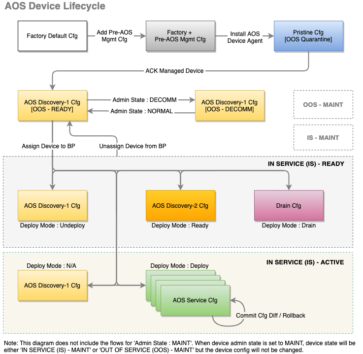
The following table describes the various config events and their resulting device config, Apstra-managed device state, and blueprint deployment mode:
| Event | Resulting Device Configuration | Resulting Apstra Managed Device State | Apstra Blueprint Deployment Mode |
|---|---|---|---|
| New device | Factory Default Configuration | N/A | N/A |
| Add pre-Apstra [mgmt] configuration to device | Factory + Pre-Apstra | N/A | N/A |
| Install Apstra device system agent | Pristine Config: Factory + Pre-Apstra + Agent Install config | OOS-QUARANTINED | Not Assigned |
| Acknowledge device | Discovery 1: Pristine, plus Interfaces Enabled | OOS-READY | Not Assigned |
| Assign device to blueprint (no deploy) | Ready (Discovery 2): Discovery 1, plus various basic config | IS-READY | Ready |
| Deploy device | Service Config: Ready (Discovery 2) config plus full Apstra-Rendered config | IS-ACTIVE | Deploy |
| Add/Commit incremental configuration | Delta of resulting config changes from blueprint modifications | IS-ACTIVE | Deploy |
| Drain device | "Drain" Configuration is added | IS-READY | Drain |
| Undeploy device | Apstra-rendered config is removed | IS-READY | Undeploy |
| Unassign device | Discovery 1 config is re-applied | OOS-READY | Not Assigned |
When you install an agent on a device, any configuration that was already there becomes part of the Pristine Config, which means it's included in the device's entire configuration lifecycle. Any corrections that you make will be service-impacting.
Configuration Stages: Detail
- New Device (Factory Default)
- Add Pre-Apstra Config (User-required)
- Install Agent (Pristine)
- Acknowledge Device (Discovery 1 / Ready)
- Assign Device (Ready / Ready)
- Deploy Device (Rendered / Active)
- Stage Device Update (Incremental / Active)
- Commit Device Again (Rendered-Updated / Active)
New Device (Factory Default)
The lifecycle of a device begins with the factory default configuration stage.
Add Pre-Apstra Config (User-required)
Certain minimum base configuration is required for the entire configuration lifecycle. This includes configuration for agent installation and device connectivity. You must configure management IP connectivity between devices and the Apstra server out-of-band (OOB). Configuring it in-band is not supported and could cause connectivity issues when changes are made to the blueprint.
You can bootstrap this User-required config with Apstra ZTP, or add it with scripts (or other methods).
Only add configuration that's required for connectivity, for installing the device agent, or that's known to be required throughout the device lifecycle (for example Banners or NTP / SNMP / syslog server IP addresses). You can add required configuration that's not rendered by Apstra with configlets.
Install Agent (Pristine)
When you install an onbox agent on a device (or an offbox agent on the server) the device connects and registers with Apstra in the Quarantined state. Apstra applies partial configuration to the pre-Apstra configuration. This configuration is called Pristine configuration. Pristine configuration is the basis for all subsequent device configuration.
Acknowledge Device (Discovery 1 / Ready)
When you acknowledge a device, you're putting it in the Ready state. This acknowledgment signals your intent to have Apstra manage the device. To the pristine config, Apstra adds minimal base configuration that's essential to Apstra agent operation. This configuration is called Discovery 1 config. Discovery 1 applies a complete configuration (Full config push), overwriting all existing configuration to ensure config integrity.
- All interfaces are rendered with interface speeds for the assigned device profile.
- All interfaces are
no shutdownto allow you to view LLDP neighbor information. - All interfaces are moved to L3 mode (default) to prevent the device from participating in the fabric.
Devices that have been acknowledged cannot simply be deleted. Since the device would still have an active agent installed, the devices would re-appear within seconds. To remove a device from Apstra management, see Remove (Decommission) Device from Managed Devices for the complete workflow.
Assign Device (Ready / Ready)
When you assign a device to a blueprint and set its Deploy Mode to Ready, you're putting it in the Ready (Discovery 2) state. The device has been staged, but not yet committed (deployed) to the active blueprint. Ready config applies a complete configuration (Full config push) to ensure config integrity. Ready configuration brings up network interfaces and configures interface descriptions and validates telemetry, such as LLDP, to ensure it's properly wired and configured. This configuration is non-disruptive to other services in the fabric. Links are up, but they are configured in L3-mode to prevent STP/L2 operations.
- Hostname is configured per blueprint intent.
- All interface descriptions are changed per blueprint intent.
- Interfaces are rendered with blueprint interface speeds.
- No routing or BGP is configured.
- No L3 information is configured on interfaces.
- Fabric MTU is modified for spine devices to 9050 bytes.
Deploy Device (Rendered / Active)
The first time you assign a device and deploy it (set deploy mode to Deploy and commit the blueprint), you're triggering a full configuration push on the device. This action overwrites the complete running configuration with the pristine configuration, then adds the full rendered Apstra configuration. Apstra discards any configuration that's not part of the Apstra-rendered configuration.
When you commit a device, it becomes Active, and Apstra deploys the service configuration, moving the device into the Rendered configuration stage. Rendered config contents are derived from the pristine config, selected reference design/topology, NOS, and device model. The first rendered config applies a complete configuration (removing all existing configuration from the Apstra server per Jinja) to ensure configuration integrity. This is the full end-state of Apstra. A full configuration has been pushed, all interfaces are running, and routing within IP fabric is configured. Full configuration rendering, intent-based telemetry, and standard service operations occur here.
- Hostname is configured per blueprint intent.
- All interface descriptions are changed per blueprint intent.
- Interfaces are rendered with blueprint interface speeds.
- Interface VLANs, LAGS, MLAG, VXLAN, and so on, are managed.
- All L3 information is rendered.
- BGP configuration is fully rendered for all BGP peering information.
- DHCP configuration is configured for any required DHCP relay agents.
- The device is added to the graph database.
After the full configuration is successfully deployed to the device, Apstra takes a snapshot of the device configuration (for example show running-confg) and stores it as the Golden Configuration.
If you add configuration at this point, you'll raise configuration deviation anomalies. The deviation is the difference between the current configuration and the stored Golden configuration. Before you can proceed with deployment tasks, you must correct any anomalies.
To see the rendered config file after committing the blueprint, select the device in the Active blueprint and click Config (right-side).
You can modify a running configuration multiple ways. To modify a config that's not part of the reference design, use configlets.
Stage Device Update (Incremental / Active)
When you stage changes to a running blueprint, you're creating an Incremental configuration.
Commit Device Again (Rendered-Updated / Active)
When you commit a change to a blueprint that affects the device's configuration, a partial config updates the rendered config.
View Device Config from Blueprint
From the blueprint, navigate to Staged > Physical to go to
the Topology view of the physical
blueprint.
Click a node in the topology, then from the Device tab in the
panel on the right, you can click links for rendered, incremental, pristine, or
device context in the Config section.

The device model is a nested dictionary of variables that you can leverage when
creating configlets in Datacenter blueprints or config templates in Freeform
blueprints. Device context includes information that's useful when creating
configlets in Data Center blueprints. In the interface section you'll find
tags for interface tags and intf_tags for link
tags. In the main section you'll find system_tags.

The query tab provides dynamic search capabilities to quickly search through keys or values and identify the variables of interest. Syntax is case-sensitive. For example, a search of the keyword bgp provides information on the BGP configuration of the switch as well as the BGP sessions (protocol sessions), while a search on the key word BGP provides the list of BGP route maps such as "BGP-AOS-Policy". The use of these variables as built-in property-sets inside a configlet must also respect the case-sensitive attribute of the device model.
Device models are an internal data model used in the Apstra environment. They are subject to change without notice or documentation of schema changes.
Configuration Deviations
After each successful config deploy the running config is collected and stored internally as the Golden configuration. Intent is the cornerstone of the Apstra product. Any difference between the actual running config and this golden config results in a config deviation anomaly on the blueprint's dashboard. The golden config is updated every time config is successfully applied to a device.
Some important points to know:
- Each successful configuration deployment results in an updated Golden Config.
- If configuration deployment fails, Golden Config is not set. This means both a config deviation and deployment failure anomaly are raised.
- Running configuration telemetry is continuously collected and matched against the Golden Config. Any difference result in a deviation anomaly.
- Configuration anomalies can be 'suppressed' using the "Accept Changes feature". This does NOT mean the change is added to golden config or Intent.
See Anomalies (Service) for details.
Manually Apply Full Config
The Discovery 1 and Deploy Device configuration stages initiate full config pushes. In rare cases, you may need to manually apply a full config push. For example, if the required config is not in place for a blueprint with NX-OS devices that require TCAM carving, the device config will fail. The TCAM config error must be corrected, followed by manually pushing a full config.
Perform a full configuration push with the utmost caution, as it is very likely to impact all services running on the box. Exact impact depends on changes being pushed. Also note all Out of Band changes are overwritten upon a full push.
Deploy Modes
Managed devices in blueprints can be in one of several modes:
Not Set
Initial device state. The device is not active in the fabric. When you unassign a system ID from a device in a blueprint, the deploy mode automatically changes to Not Set (as of Apstra version 5.0.0).
Deploy
The device is active in the fabric.
Ready
When you assign a device to a blueprint, it's deploy mode changes to Ready; Apstra renders Ready (Discovery 2) configuration (hostnames, interface descriptions, port speed / breakout configuration). The device isn't active in the fabric. Changing from Deploy to Ready removes Apstra-rendered configuration.
Drain
Draining a device for physical maintenance enables it to be taken out of service without impacting existing TCP flows. Depending on the device being drained, Apstra uses one of two methods:
For L2 Servers
- MLAG peer-links port channels and bond interfaces on any NOS are not changed.
- For Arista EOS and Cisco NX-OS, and Junos OS on Apstra 4.2.1 and above, all
interfaces towards L2 servers in the blueprint are
shutdown.
For Network L3 Switches
The device uses Inbound/Outbound route-maps 'deny' statements to block any advertisements to 0.0.0.0/0 le 32. This allows existing L3 TCP flows to continue without interruption. After a second or two, the TCP sessions should be re-established by the src/dst devices, or they should negotiate a new TCP port. The new TCP port forces the devices to be hashed onto a new ECMP path from the list of available links. Since no ECMP routes to the destination are available in the presence of a route map, the traffic does not flow through the device that is in Drain mode. The device is effectively drained of traffic and can be removed from the fabric (by changing Deploy mode to Undeploy).
While TCP sessions drain (which could take some time, especially for EVPN blueprints) BGP anomalies are expected. When configuration deployment is complete, the temporary anomalies are resolved.
When you change the deploy mode to Drain on a device, neighboring device configuration may also be affected, not just the device you're draining. For example, when you drain a spine device, configuration on all connected leaf devices change. Neighboring leaf devices use Inbound/Outbound route filters (route-maps) 'reject (deny)' statements to block any advertisements to 0.0.0.0/0 le 32, for both EVPN (overlay) and FABRIC (underlay).

Similarly, when you drain a leaf device, the configuration on connected spine devices changes. Neighboring spine devices use Inbound/Outbound route filters (route-maps) 'reject (deny)' statements to block any advertisements to 0.0.0.0/0 le 32, for both EVPN (overlay) and FABRIC (underlay).

In the case of an MLAG-based topology, in addition to the configuration on connected spine devices changing, the configuration on the paired leaf device also changes.

Undeploy
Undeploying a device removes the complete service configuration. If a device is carrying traffic it is best to put it in Drain mode first (and commit the change) before undeploying the device.