Example: Configure an RFC 2544-Based Benchmarking Test for Layer 3 IPv4 Services
This example shows how to configure the benchmarking test for a Layer 3 IPv4 service.
This example is not applicable for ACX5448, ACX5048, and ACX5096 routers.
Requirements
This example uses the following hardware and software components:
An ACX Series router
Junos OS Release 12.3X53 or later
Overview
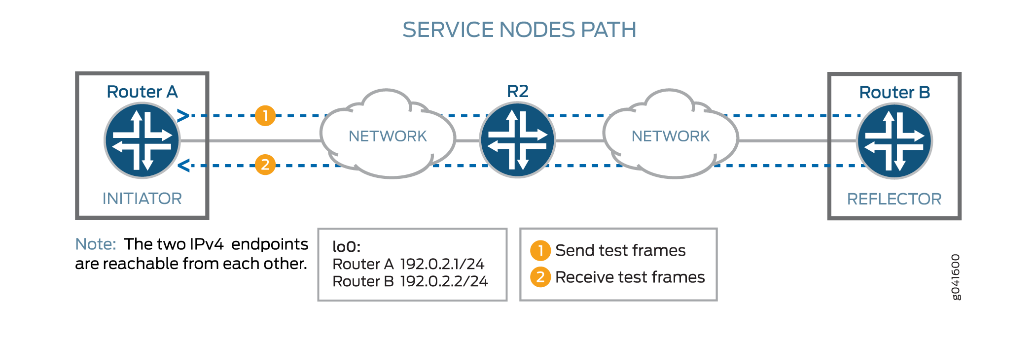
Consider a sample topology in which a router, Router A, functions as an initiator and terminator of the test frames for an RFC 2544-based benchmarking test. Router A is connected over a Layer 3 network to another router, Router B, which functions as a reflector to reflect back the test frames it receives from Router A. IPv4 is used for transmission of test frames over the Layer 3 network. This benchmarking test is used to compute the IPv4 service parameters between Router A and Router B. Logical interfaces on both the routers are configured with IPv4 addresses to measure the performance attributes, such as throughput, latency, frame loss, and bursty frames, of network devices for the IPv4 service.
Figure 1 shows the sample topology to perform an RFC 2544 test for a Layer 3 IPv4 service.
Configuration
In this example, you configure the benchmarking test for a Layer 3 IPv4 service that is between interface ge-0/0/0 on Router A and interface ge-0/0/4 on Router B to detect and analyze the performance of the interconnecting routers. You do not configure a test profile on Router B, because it operates as a reflector. You must configure the reflector (Router B) before you configure the initiator (Router A), because the reflector needs to be already configured and the tests running before you start tests on the initiator. If you start the tests on the initiator first, then all the packets sent are lost until you start the tests on the reflector.
- CLI Quick Configuration
- Configure Benchmarking Test Parameters on Router B
- Configure Benchmarking Test Parameters on Router A
- Results
CLI Quick Configuration
To quickly configure this example, copy the following commands, paste them in a
text file, remove any line breaks, change any details necessary to match your
network configuration, and then copy and paste the commands into the CLI at the
[edit] hierarchy level:
Configure Benchmarking Test Parameters on Router B
set interfaces ge-0/0/4 unit 0 family inet address 192.0.2.2/24
set services rpm rfc2544-benchmarking tests test-name test1 test-interface ge-0/0/4.0
set services rpm rfc2544-benchmarking tests test-name test1 mode reflect
set services rpm rfc2544-benchmarking tests test-name test1 family inet
set services rpm rfc2544-benchmarking tests test-name test1 destination-ipv4-address 192.0.2.2
set services rpm rfc2544-benchmarking tests test-name test1 destination-udp-port 4001
set rfc2544-benchmarking tests test-name test1 source-ipv4-address 192.0.2.1
Configure Benchmarking Test Parameters on Router A
set interfaces ge-0/0/0 unit 0 family inet address 192.0.2.1/24
set rfc2544-benchmarking profiles test-profile throughput test-type throughput
set rfc2544-benchmarking profiles test-profile throughput packet-size 64
set rfc2544-benchmarking profiles test-profile throughput bandwidth-kbps 1000
set rfc2544-benchmarking tests test-name test1 test-profile throughput
set rfc2544-benchmarking tests test-name test1 test-interface ge-0/0/0.0
set rfc2544-benchmarking tests test-name test1 mode initiate-and-terminate
set rfc2544-benchmarking tests test-name test1 family inet
set rfc2544-benchmarking tests test-name test1 destination-ipv4-address 192.0.2.2
set rfc2544-benchmarking tests test-name test1 destination-udp-port 4001
set rfc2544-benchmarking tests test-name test1 source-ipv4-address 192.0.2.1
Configure Benchmarking Test Parameters on Router B
Step-by-Step Procedure
The following example requires you to navigate various levels in the configuration hierarchy. For information about navigating the CLI, see Using the CLI Editor in Configuration Mode.
To configure the test parameters on Router B:
-
In configuration mode, go to the
[edit interfaces]hierarchy level:[edit] user@RouterB# edit interfaces
-
Configure the interface on which the test must be run.
[edit interfaces]
user@RouterB# edit ge-0/0/4
-
Configure a logical unit and specify the protocol family as
inet.[edit interfaces ge-0/0/4] user@RouterB# edit unit 0 family inet
-
Specify the address for the logical interface.
[edit interfaces ge-0/0/4 unit 0 family inet]
user@RouterB# set address 192.0.2.2/24
-
Enter the
upcommand to go the previous level in the configuration hierarchy.[edit interfaces ge-0/0/4 unit 0 family inet] user@RouterB# up
-
Go to the top level of the configuration mode.
[edit interfaces ge-0/0/4 unit 0]
user@RouterB# top
-
In configuration mode, go to the
[edit services]hierarchy level.[edit] user@RouterB# edit services
-
Configure a real-time performance monitoring service (RPM) instance.
[edit services]
user@RouterB# edit rpm
-
Configure an RFC 2544-based benchmarking test for the RPM instance.
[edit services rpm]
user@RouterB# edit rfc2544-benchmarking
-
Define a name for the test—for example, test1. The test name identifier can be up to 32 characters in length.
[edit services rpm rfc2544-benchmarking]
user@RouterB# edit tests test-name test1
-
Specify the logical interface, ge-0/0/4.0, on which the RFC 2544-based benchmarking test is run.
[edit services rpm rfc2544-benchmarking tests test-name test1]
user@RouterB# set test-interface ge-0/0/4.0
-
Specify
reflectas the test mode for the packets that are sent during the benchmarking test.[edit services rpm rfc2544-benchmarking tests test-name test1] user@RouterB# set mode reflect
-
Configure the address type family,
inet, for the benchmarking test.[edit services rpm rfc2544-benchmarking tests test-name test1] user@RouterB# set family inet
-
Configure the destination IPv4 address for the test packets as 192.0.2.2. The destination IPv4 address configured on the reflector must match the destination IPv4 address configured on the initiator. If you configure 192.0.2.1 instead, you get this error message:
error: test test1 - Could not determine local interface for address 192.0.2.1.[edit services rpm rfc2544-benchmarking tests test-name test1] user@RouterB# set destination-ipv4-address 192.0.2.2
-
Specify the UDP port of the destination to be used in the UDP header for the generated frames as 4001.
[edit services rpm rfc2544-benchmarking tests test-name test1]
user@RouterB# set destination-udp-port 4001
-
Configure the source IPv4 address for the test packets.
[edit services rpm rfc2544-benchmarking tests test-name test1]
user@RouterB# set source-ipv4-address 192.0.2.1
-
Go to the top level of the configuration mode.
[edit services rpm rfc2544-benchmarking tests test-name test1]
user@RouterB# top
-
Commit the configuration.
[edit]
user@RouterB# commit
-
Confirm the configuration. If the output does not contain the configuration below, repeat the configuration instructions in this example to correct it.
[edit interfaces] ge-0/0/4 { unit 0 { family inet { address 192.0.2.2/24; } } } [edit services rpm] rfc2544-benchmarking { # Note, When in reflector mode, test profile is not needed tests { test-name test1 { test-interface ge-0/0/4.0; mode reflect; family inet; destination-ipv4-address 192.0.2.2; destination-udp-port 4001; source-ipv4-address 192.0.2.1 } } } -
Exit to operational mode.
[edit]
user@RouterB# exit
user@RouterB>
-
Start the benchmarking test on the reflector.
user@RouterB> test services rpm rfc2544-benchmarking test test1 start
Once you configure the initiator (Router A), you can start the test on the initiator, and the initiator starts sending packets to the reflector. Once the test is successfully completed at the initiator, you can stop the test at the reflector by entering the
test
                                    services rpm rfc2544-benchmarking test test1 stop
command in operational mode.
Configure Benchmarking Test Parameters on Router A
Step-by-Step Procedure
The following example requires you to navigate various levels in the configuration hierarchy. For information about navigating the CLI, see Using the CLI Editor in Configuration Mode.
To configure the test parameters on Router A:
-
In configuration mode, go to the
[edit interfaces]hierarchy level:[edit] user@RouterA# edit interfaces
-
Configure the interface on which the test must be run.
[edit interfaces]
user@RouterA# edit ge-0/0/0
-
Configure a logical unit and specify the protocol family.
[edit interfaces ge-0/0/0]
 user@RouterA# edit unit 0 family inet
-
Specify the address for the logical interface.
[edit interfaces ge-0/0/0 unit 0 family inet]
user@RouterA# set address 192.0.2.1/24
-
Enter the
upcommand to go the previous level in the configuration hierarchy.[edit interfaces ge-0/0/0 unit 0 family inet] user@RouterA# up
-
Go to the top level of the configuration command mode.
[edit interfaces ge-0/0/0 unit 0]
user@RouterA# top
-
In configuration mode, go to the
[edit services]hierarchy level.[edit] user@RouterA# edit services
-
Configure a real-time performance monitoring service (RPM) instance.
[edit services]
user@RouterA# edit rpm
-
Configure an RFC 2544-based benchmarking test for the RPM instance.
[edit services rpm]
user@RouterA# edit rfc2544-benchmarking
-
Define a name for a test profile—for example, throughput.
[edit services rpm rfc2544-benchmarking]
user@RouterA# edit profiles test-profile throughput
-
Configure the type of test to be performed as throughput.
[edit services rpm rfc2544-benchmarking profiles test-profile throughput]
user@RouterA# set test-type throughput
-
Specify the size of the test packet as 64 bytes.
[edit services rpm rfc2544-benchmarking profiles test-profile throughput]
user@RouterA# set test-type packet-size 64
-
Define the theoretical maximum bandwidth for the test in kilobits per second, with a value from 1,000 Kbps through 1,000,000 Kbps.
[edit services rpm rfc2544-benchmarking profiles test-profile throughput]
user@RouterA# set test-type bandwidth-kbps 1000
-
Enter the
upcommand to go the previous level in the configuration hierarchy.[edit services rpm rfc2544-benchmarking profiles test-profile throughput] user@RouterA# up
-
Enter the
upcommand to go the previous level in the configuration hierarchy.[edit services rpm rfc2544-benchmarking profiles] user@RouterA# up
-
Define a name for the test—for example, test1. The test name identifier can be up to 32 characters in length.
[edit services rpm rfc2544-benchmarking]
user@RouterA# edit tests test-name test1
-
Specify the name of the test profile—for example, throughput—to be associated with a particular test name.
[edit services rpm rfc2544-benchmarking tests test-name test1]
user@RouterA# set test-profile throughput
-
Specify the logical interface, ge-0/0/0.0, on which the RFC 2544-based benchmarking test is run.
[edit services rpm rfc2544-benchmarking tests test-name test1]
user@RouterA# set test-interface ge-0/0/0.0
-
Specify the test mode for the packets that are sent during the benchmarking test as initiate and terminate.
[edit services rpm rfc2544-benchmarking tests test-name test1]
user@RouterA# set mode initiate-and-terminate
-
Configure the address type family,
inet, for the benchmarking test.[edit services rpm rfc2544-benchmarking tests test-name test1] user@RouterA# set family inet
-
Configure the destination IPv4 address for the test packets.
[edit services rpm rfc2544-benchmarking tests test-name test1]
user@RouterA# set destination-ipv4-address 192.0.2.2
-
Specify the UDP port of the destination to be used in the UDP header for the generated frames as 4001.
[edit services rpm rfc2544-benchmarking tests test-name test1]
user@RouterA# set destination-udp-port 4001
-
Configure the source IPv4 address for the test packets.
[edit services rpm rfc2544-benchmarking tests test-name test1]
user@RouterA# set source-ipv4-address 192.0.2.1
-
Go to the top level of the configuration mode.
[edit services rpm rfc2544-benchmarking tests test-name test1]
user@RouterA# top
-
Commit the configuration.
[edit]
user@RouterA# commit
-
Confirm the configuration. If the output does not contain the configuration below, repeat the configuration instructions in this example to correct it.
[edit] user@RouterA# show [edit interfaces] ge-0/0/0 { unit 0 { family inet { address 192.0.2.1/24; } } } [edit services rpm] rfc2544-benchmarking { profiles { test-profile throughput { test-type throughput packet-size 64; bandwidth-kbps 1000; } } tests { test-name test1 { test-profile throughput; interface ge-0/0/0.0; mode initiate-and-terminate; family inet; destination-ipv4-address 192.0.2.2 destination-udp-port 4001; source-ipv4-address 192.0.2.1 } } } -
Exit to operational mode.
[edit]
user@RouterA# exit
user@RouterA>
-
Start the benchmarking test on the initiator.
user@RouterA> test services rpm rfc2544-benchmarking test test1 start
After the test successfully completes, it automatically stops at the initiator. Once the test is successfully completed at the initiator, you can stop the test at the reflector by entering the
test
                                    services rpm rfc2544-benchmarking test test1 stop
command on Router B in operational mode.
Results
If you have not done so already, confirm your configuration on Router A and
Router B by entering the show command in configuration mode at
the [edit interfaces] and [edit services rpm] hierarchy levels. If the output
does not display the intended configuration, repeat the configuration
instructions in this example to correct it.
Configuration for Benchmarking Test Parameters on Router A:
[edit interfaces]
  ge-0/0/0 {
      unit 0 {
          family inet {
              address 192.0.2.1/24;
          }
       }
  }

  [edit services rpm]
  rfc2544-benchmarking {
      profiles {
          test-profile throughput {
              test-type throughput
              packet-size 64;
              bandwidth-kbps 1000;
          }
      }

      tests {
          test-name test1 {
              test-profile throughput;
              interface ge-0/0/0.0;
              mode initiate-and-terminate;
              family inet;
              destination-ipv4-address 192.0.2.2
              destination-udp-port 4001;
              source-ipv4-address 192.0.2.1
          }
      }
  }
Configuration for Benchmarking Test Parameters on Router B:
[edit interfaces]
  ge-0/0/4 {
      unit 0 {
          family inet {
              address 192.0.2.2/24;
          }
       }
  }

  [edit services rpm]
  rfc2544-benchmarking {
      # Note, When in reflector mode, test profile is not needed
      tests {
          test-name test1 {
              test-interface ge-0/0/4.0;
              mode reflect;
              family inet;
              destination-ipv4-address 192.0.2.2;
              destination-udp-port 4001;
              source-ipv4-address 192.0.2.1
          }
      }
  }
Verify the Results of the Benchmarking Test for Layer 3 IPv4 Services
Examine the results of the benchmarking test performed on the configured service between Router A and Router B.
Verify the Benchmarking Test Results
Purpose
Verify that the necessary and desired statistical values are displayed for the benchmarking test that is run on the configured service between Router A and Router B.
Action
In operational mode, enter the show services rpm rfc2544-benchmarking
(aborted-tests | active-tests | completed-tests | summary)
command, on either the initiator or the reflector, to display information
about the results of each category or state of the RFC 2544-based
benchmarking test, such as terminated tests, active tests, and completed
tests, for each real-time performance monitoring (RPM) instance.
Meaning
The output displays the details of the benchmarking test that was performed.