ON THIS PAGE
Example: Configuring Routing Policy Prefix Lists
In Junos OS, prefix lists provide one method of defining a set of routes. Junos OS
provides other methods of accomplishing the same task, such as route filters. A prefix
list is a listing of IP prefixes that represent a set of routes that are used as match
criteria in an applied policy. Such a list might be useful for representing a list of
customer routes in your autonomous system (AS). A prefix list is given a name and is
configured within the [edit policy-options] configuration hierarchy.
Requirements
No special configuration beyond device initialization is required before configuring this example.
Updated and re-validated using Junos OS Release 22.1R1.
Overview
Prefix lists are similar to a list of route filters. The functional difference
between route filters and prefix lists is that you cannot specify a range using a
prefix list. You can simulate a range using a prefix list by including additional
prefixes in the list, or by using two prefix lists, one shorter and one longer,
setting one to accept and the other to reject. You can also filter a prefix list
using the prefix-list-filter match condition. Your choices are
exact, longer, and orlonger.
The benefit of a prefix list over a list of route filters is seen when the prefixes are referenced in several different locations. For instance, a prefix list can be referenced in a BGP import policy, an export policy, an RPF policy, in firewall filters, in loopback filters, in setting a multicast scope, and so on.
When your list of prefixes changes, rather than trying to remember the many different locations prefixes are configured, you can instead update the prefix list, changing the prefix one time instead of multiple times. This helps to reduce the likelihood of configuration errors, such as mistyping the address in a location or forgetting to update one or more locations.
Prefix lists also help when managing a large number of devices. You can write the various filters and policies as generically as possible, referencing prefix lists instead of specific IP addresses. The more complex logic in the filters and policies has to be written only one time, with minimal per-device and per-site customizations.
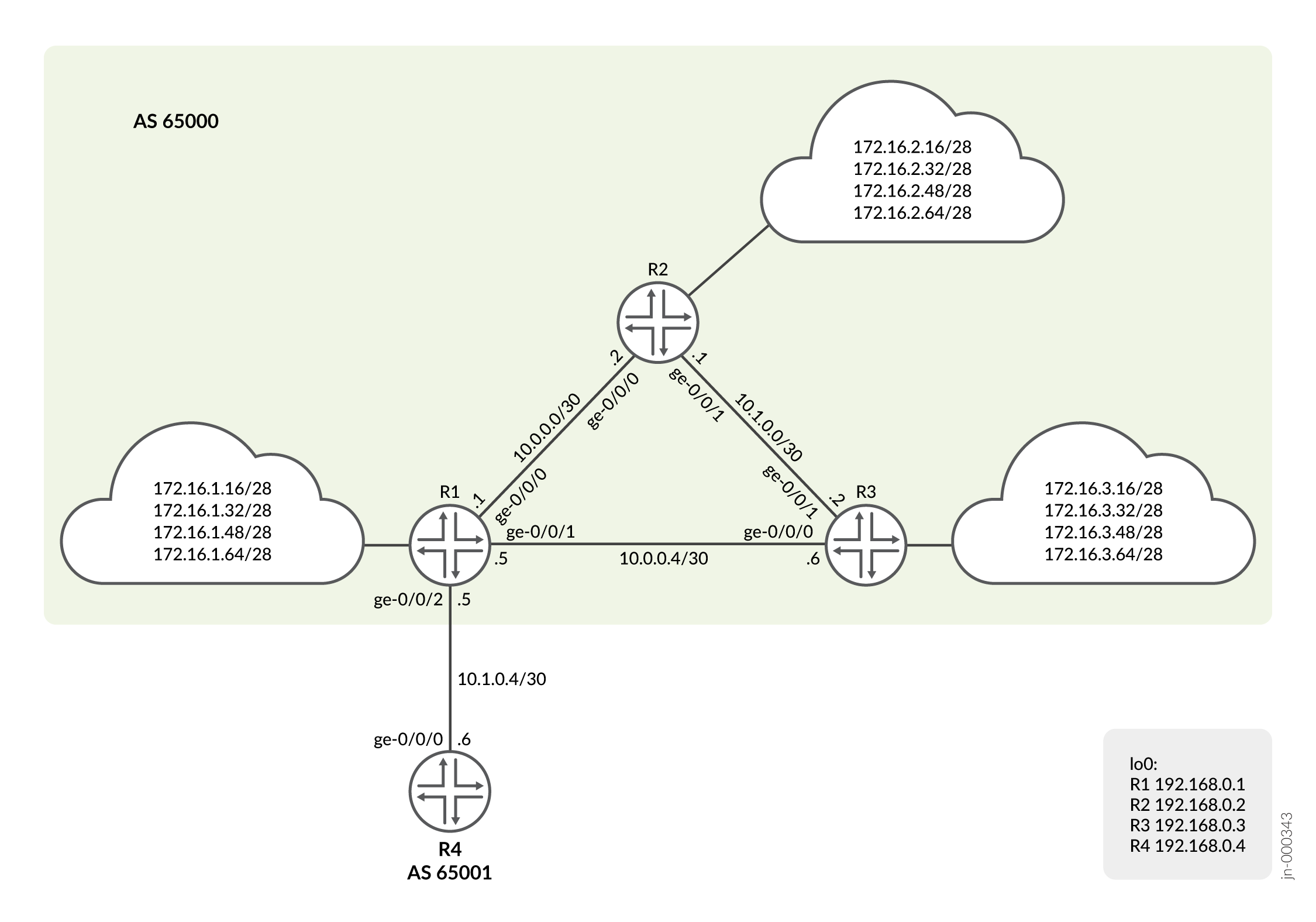
As shown in Figure 1, each
router
in AS
65000
has customer routes. Device R1 assigns customer routes within the 172.16.1.0/24
subnet. Device R2 and Device R3 assign customer routes within the 172.16.2.0/24 and
172.16.3.0/24 subnets, respectively. Device R1 has been designated the central point
in AS
65000
to maintain a complete list of customer routes. Device R1 has a prefix list called
customers, as follows:
user@R1# show policy-options
prefix-list customers {
    172.16.1.16/28;
    172.16.1.32/28;
    172.16.1.48/28;
    172.16.1.64/28;
    172.16.2.16/28;
    172.16.2.32/28;
    172.16.2.48/28;
    172.16.2.64/28;
    172.16.3.16/28;
    172.16.3.32/28;
    172.16.3.48/28;
    172.16.3.64/28;
}
As you can see, the prefix list does not contain a match type for each route (as you would see with a route filter). This is an important point when using a prefix list in a policy. Routes match only if they exactly match one of the prefixes in the list. In other words, each route in the list must appear in the routing table exactly as it is configured in the prefix list.
You reference the prefix list as a match criterion within a policy like this:
user@R1# show policy-options
policy-statement customer-routes {
    term get-routes {
        from {
            prefix-list customers;
        }
        then accept;
    }
    term others {
        then reject;
    }
}
In this example, all the routes in the customers prefix list appear
in the routing table on Device R1. Device R2 and Device R3 export to Device R1
static routes to their customers.
As previously mentioned, you can use the prefix-list-filter match
condition with the exact, longer, or
orlonger match type. This provides a way to avoid the prefix
list exact-match limitation of prefix lists. For example:
user@R1# show policy-options
policy-statement customer-routes {
    term get-routes {
        from {
            prefix-list-filter customers orlonger;
        }
        then accept;
    }
    term others {
        then reject;
    }
}
The example demonstrates the effects of both the prefix-list match
condition and the prefix-list-filter match condition.
Topology
Figure 1 shows the sample network.
CLI Quick Configuration shows the configuration for all of the devices in Figure 1.
The section #configuration449__policy-prefix-list-st describes the steps on Device R1.
Configuration
CLI Quick Configuration
To quickly configure this example, copy the following commands, paste them into a
text file, remove any line breaks, change any details necessary to match your
network configuration, and then copy and paste the commands into the CLI at the
[edit] hierarchy level.
Device R1
set interfaces ge-0/0/0 unit 0 description to_R2
set interfaces ge-0/0/0 unit 0 family inet address 10.0.0.1/30
set interfaces ge-0/0/1 unit 0 description to_R3
set interfaces ge-0/0/1 unit 0 family inet address 10.0.0.5/30
set interfaces ge-0/0/2 unit 0 description to_R4
set interfaces ge-0/0/2 unit 0 family inet address 10.1.0.5/30
set interfaces lo0 unit 0 family inet address 192.168.0.1/32
set policy-options prefix-list customers 172.16.1.16/28
set policy-options prefix-list customers 172.16.1.32/28
set policy-options prefix-list customers 172.16.1.48/28
set policy-options prefix-list customers 172.16.1.64/28
set policy-options prefix-list customers 172.16.2.16/28
set policy-options prefix-list customers 172.16.2.32/28
set policy-options prefix-list customers 172.16.2.48/28
set policy-options prefix-list customers 172.16.2.64/28
set policy-options prefix-list customers 172.16.3.16/28
set policy-options prefix-list customers 172.16.3.32/28
set policy-options prefix-list customers 172.16.3.48/28
set policy-options prefix-list customers 172.16.3.64/28
set policy-options policy-statement customer-routes term get-routes from prefix-list customers
set policy-options policy-statement customer-routes term get-routes then accept
set policy-options policy-statement customer-routes term others then reject
set routing-options router-id 192.168.0.1
set routing-options autonomous-system 65000
set routing-options static route 172.16.1.16/28 discard
set routing-options static route 172.16.1.32/28 discard
set routing-options static route 172.16.1.48/28 discard
set routing-options static route 172.16.1.64/28 discard
set protocols bgp group int type internal
set protocols bgp group int local-address 192.168.0.1
set protocols bgp group int neighbor 192.168.0.2
set protocols bgp group int neighbor 192.168.0.3
set protocols bgp group to_65001 type external
set protocols bgp group to_65001 export customer-routes
set protocols bgp group to_65001 neighbor 10.1.0.6 peer-as 65001
set protocols ospf area 0.0.0.0 interface ge-0/0/0.0
set protocols ospf area 0.0.0.0 interface ge-0/0/1.0
set protocols ospf area 0.0.0.0 interface lo0.0 passive
Device R2
set interfaces ge-0/0/0 unit 0 description to_R1
set interfaces ge-0/0/0 unit 0 family inet address 10.0.0.2/30
set interfaces ge-0/0/1 unit 0 description to_R3
set interfaces ge-0/0/1 unit 0 family inet address 10.1.0.1/30
set interfaces lo0 unit 0 family inet address 192.168.0.2/32
set policy-options policy-statement send-static term 1 from protocol static
set policy-options policy-statement send-static term 1 then accept
set routing-options router-id 192.168.0.2
set routing-options autonomous-system 65000
set routing-options static route 172.16.2.16/28 discard
set routing-options static route 172.16.2.32/28 discard
set routing-options static route 172.16.2.48/28 discard
set routing-options static route 172.16.2.64/28 discard
set protocols bgp group int type internal
set protocols bgp group int local-address 192.168.0.2
set protocols bgp group int neighbor 192.168.0.1 export send-static
set protocols bgp group int neighbor 192.168.0.3
set protocols ospf area 0.0.0.0 interface ge-0/0/0.0
set protocols ospf area 0.0.0.0 interface ge-0/0/1.0
set protocols ospf area 0.0.0.0 interface lo0.0 passive
Device R3
set interfaces ge-0/0/0 unit 0 description to_R1
set interfaces ge-0/0/0 unit 0 family inet address 10.0.0.6/30
set interfaces ge-0/0/1 unit 0 description to_R2
set interfaces ge-0/0/1 unit 0 family inet address 10.1.0.2/30
set interfaces lo0 unit 0 family inet address 192.168.0.3/32
set policy-options policy-statement send-static term 1 from protocol static
set policy-options policy-statement send-static term 1 then accept
set routing-options router-id 192.168.0.3
set routing-options autonomous-system 65000
set routing-options static route 172.16.3.16/28 discard
set routing-options static route 172.16.3.32/28 discard
set routing-options static route 172.16.3.48/28 discard
set routing-options static route 172.16.3.64/28 discard
set protocols bgp group int type internal
set protocols bgp group int local-address 192.168.0.3
set protocols bgp group int neighbor 192.168.0.1 export send-static
set protocols bgp group int neighbor 192.168.0.2
set protocols ospf area 0.0.0.0 interface ge-0/0/0.0
set protocols ospf area 0.0.0.0 interface ge-0/0/1.0
set protocols ospf area 0.0.0.0 interface lo0.0 passive
Device R4
set interfaces ge-0/0/0 unit 0 description to_R1
set interfaces ge-0/0/0 unit 0 family inet address 10.1.0.6/30
set interfaces lo0 unit 0 family inet address 192.168.0.4/32
set routing-options autonomous-system 65001
set protocols bgp group ext type external
set protocols bgp group ext peer-as 65000
set protocols bgp group ext neighbor 10.1.0.5
Procedure
Step-by-Step Procedure
We are showing the step-by-step procedure to configure R1. The other routers have a similar step-by-step process. The following example requires that you navigate various levels in the configuration hierarchy. For information about navigating the CLI, see Use the CLI Editor in Configuration Mode in the Junos OS CLI User Guide.
To configure R1:
-
Configure the interfaces.
[edit]
user@R1# set interfaces ge-0/0/0 unit 0 description to_R2
user@R1# set interfaces ge-0/0/0 unit 0 family inet address 10.0.0.1/30
user@R1# set interfaces ge-0/0/1 unit 0 description to_R3
user@R1# set interfaces ge-0/0/1 unit 0 family inet address 10.0.0.5/30
user@R1# set interfaces ge-0/0/2 unit 0 description to_R4
user@R1# set interfaces ge-0/0/2 unit 0 family inet address 10.1.0.5/30
user@R1# set interfaces lo0 unit 0 family inet address 192.168.0.1/32
-
Configure the internal BGP (IBGP) peerings to R2 and R3.
[edit]
user@R1# set protocols bgp group int type internal
user@R1# set protocols bgp group int local-address 192.168.0.1
user@R1# set protocols bgp group int neighbor 192.168.0.2
user@R1# set protocols bgp group int neighbor 192.168.0.3
-
Configure the external BGP (EBGP) peering to R4. The export policy configuration is shown in a later step.
[edit]
user@R1# set protocols bgp group to_65001 type external
user@R1# set protocols bgp group to_65001 export customer-routes
user@R1# set protocols bgp group to_65001 neighbor 10.1.0.6 peer-as 65001
-
Configure the OSPF peerings to R2 and R3. The OSPF protocol provides the learning of the loopback address for each device which allows the IBGP peerings to establish.
[edit]
user@R1# set protocols ospf area 0.0.0.0 interface ge-0/0/0.0
user@R1# set protocols ospf area 0.0.0.0 interface ge-0/0/1.0
user@R1# set protocols ospf area 0.0.0.0 interface lo0.0 passive
-
Configure the prefix list.
[edit]
user@R1# set policy-options prefix-list customers 172.16.1.16/28
user@R1# set policy-options prefix-list customers 172.16.1.32/28
user@R1# set policy-options prefix-list customers 172.16.1.48/28
user@R1# set policy-options prefix-list customers 172.16.1.64/28
user@R1# set policy-options prefix-list customers 172.16.2.16/28
user@R1# set policy-options prefix-list customers 172.16.2.32/28
user@R1# set policy-options prefix-list customers 172.16.2.48/28
user@R1# set policy-options prefix-list customers 172.16.2.64/28
user@R1# set policy-options prefix-list customers 172.16.3.16/28
user@R1# set policy-options prefix-list customers 172.16.3.32/28
user@R1# set policy-options prefix-list customers 172.16.3.48/28
user@R1# set policy-options prefix-list customers 172.16.3.64/28
-
Configure the routing policy that references the prefix list as a match criterion.
[edit]
user@R1# set policy-options policy-statement customer-routes term get-routes from prefix-list customers
user@R1# set policy-options policy-statement customer-routes term get-routes then accept
user@R1# set policy-options policy-statement customer-routes term others then reject
-
Configure the static routes for the 172.16.1.0/24 network. We are using static routes to emulate the customer routes.
[edit]
user@R1# set routing-options static route 172.16.1.16/28 discard
user@R1# set routing-options static route 172.16.1.32/28 discard
user@R1# set routing-options static route 172.16.1.48/28 discard
user@R1# set routing-options static route 172.16.1.64/28 discard
-
Configure the autonomous system (AS) number and router ID.
[edit]
user@R1# set routing-options router-id 192.168.0.1
user@R1# set routing-options autonomous-system 65000
Results
From configuration mode, confirm your configuration by entering the
show interfaces, show protocols,
show policy-options, and show
routing-options commands. If the output does not display the
intended configuration, repeat the instructions in this example to correct
the configuration.
user@R1# show interfaces
ge-0/0/0 {
    unit 0 {
        description to_R2;
        family inet {
            address 10.0.0.1/30;
        }
    }
}
ge-0/0/1 {
    unit 0 {
        description to_R3;
        family inet {
            address 10.0.0.5/30;
        }
    }
}
ge-0/0/2 {
    unit 0 {
        description to_R4;
        family inet {
            address 10.1.0.5/30;
        }
    }
}
lo0 {
    unit 0 {
        family inet {
            address 192.168.0.1/32;
        }
    }
}user@R1# show protocols
bgp {
group int {
type internal;
local-address 192.168.0.1;
neighbor 192.168.0.2;
neighbor 192.168.0.3;
}
group to_65001 {
type external;
export customer-routes;
neighbor 10.1.0.6 {
peer-as 65001;
}
}
}
ospf {
area 0.0.0.0 {
interface ge-0/0/0.0;
interface ge-0/0/1.0;
interface lo0.0 {
passive;
}
}
}user@R1# show policy-options
prefix-list customers {
172.16.1.16/28;
172.16.1.32/28;
172.16.1.48/28;
172.16.1.64/28;
172.16.2.16/28;
172.16.2.32/28;
172.16.2.48/28;
172.16.2.64/28;
172.16.3.16/28;
172.16.3.32/28;
172.16.3.48/28;
172.16.3.64/28;
}
policy-statement customer-routes {
term get-routes {
from {
prefix-list customers;
}
then accept;
}
term others {
then reject;
}
}
user@R1# show routing-options
static {
    route 172.16.1.16/28 discard;
    route 172.16.1.32/28 discard;
    route 172.16.1.48/28 discard;
    route 172.16.1.64/28 discard;
}
router-id 192.168.0.1;
autonomous-system 65000;
If you are done configuring the device, enter commit from
configuration mode.
Verification
Confirm that the configuration is working properly.
- Verifying the Routes on R1
- Verifying the Route Advertisement to R4
- Experimenting with the prefix-list-filter Statement
Verifying the Routes on R1
Purpose
On R1, check the routes in the routing table.
Action
user@R1> show route terse 172.16/16

inet.0: 30 destinations, 30 routes (30 active, 0 holddown, 0 hidden)
+ = Active Route, - = Last Active, * = Both

A V Destination        P Prf   Metric 1   Metric 2  Next hop        AS path
* ? 172.16.1.16/28     S   5                        Discard
* ? 172.16.1.32/28     S   5                        Discard
* ? 172.16.1.48/28     S   5                        Discard
* ? 172.16.1.64/28     S   5                        Discard
* ? 172.16.2.16/28     B 170        100                             I
  unverified                                       >10.0.0.2
* ? 172.16.2.32/28     B 170        100                             I
  unverified                                       >10.0.0.2
* ? 172.16.2.48/28     B 170        100                             I
  unverified                                       >10.0.0.2
* ? 172.16.2.64/28     B 170        100                             I
  unverified                                       >10.0.0.2
* ? 172.16.3.16/28     B 170        100                             I
  unverified                                       >10.0.0.6
* ? 172.16.3.32/28     B 170        100                             I
  unverified                                       >10.0.0.6
* ? 172.16.3.48/28     B 170        100                             I
  unverified                                       >10.0.0.6
* ? 172.16.3.64/28     B 170        100                             I
  unverified                                       >10.0.0.6
Meaning
Device R1 has learned its own static routes (S) and the BGP routes from Devices R2 and R3 (B).
Verifying the Route Advertisement to R4
Purpose
On R1, make sure that the customer routes are advertised to R4.
Action
user@R1> show route advertising-protocol bgp 10.1.0.6

inet.0: 30 destinations, 30 routes (30 active, 0 holddown, 0 hidden)
  Prefix                  Nexthop              MED     Lclpref    AS path
* 172.16.1.16/28          Self                                    I
* 172.16.1.32/28          Self                                    I
* 172.16.1.48/28          Self                                    I
* 172.16.1.64/28          Self                                    I
* 172.16.2.16/28          Self                                    I
* 172.16.2.32/28          Self                                    I
* 172.16.2.48/28          Self                                    I
* 172.16.2.64/28          Self                                    I
* 172.16.3.16/28          Self                                    I
* 172.16.3.32/28          Self                                    I
* 172.16.3.48/28          Self                                    I
* 172.16.3.64/28          Self                                    I
Meaning
As expected, only the routes from the customer prefix list are advertised to R4.
Experimenting with the prefix-list-filter Statement
Purpose
See what can happen when you use prefix-list-filter instead
of prefix-list.
Action
-
On R3, add a static route that is longer than one of the existing static routes.
[edit routing-options static]
user@R3# set route 172.16.3.65/32 discard
user@R3# commit
-
On R1, deactivate the prefix list and configure a prefix list filter with the
orlongermatch type.[edit policy-options policy-statement customer-routes term get-routes] user@R1# deactivate from prefix-list customers user@R1# set from prefix-list-filter customers orlonger user@R1# commit
-
On R1, check which routes are advertised to R4.
user@R1> show route advertising-protocol bgp 10.1.0.6

inet.0: 31 destinations, 31 routes (31 active, 0 holddown, 0 hidden)
  Prefix                  Nexthop              MED     Lclpref    AS path
* 172.16.1.16/28          Self                                    I
* 172.16.1.32/28          Self                                    I
* 172.16.1.48/28          Self                                    I
* 172.16.1.64/28          Self                                    I
* 172.16.2.16/28          Self                                    I
* 172.16.2.32/28          Self                                    I
* 172.16.2.48/28          Self                                    I
* 172.16.2.64/28          Self                                    I
* 172.16.3.16/28          Self                                    I
* 172.16.3.32/28          Self                                    I
* 172.16.3.48/28          Self                                    I
* 172.16.3.64/28          Self                                    I
* 172.16.3.65/32          Self                                    I
Meaning
As expected, R1 is now advertising the 172.16.3.65/32 route to R4, even though 172.16.3.65/32 is not in the prefix list.