Migrate a Traditional Enterprise Network to a Juniper Campus Fabric
Use this information (including a video, diagrams, and a high-level workflow) to learn about migrating to a Campus Fabric architecture.
This document details a strategy that can be used to migrate a traditional enterprise network-based architecture to a Juniper Campus Fabric EVPN-VXLAN architecture.
Juniper’s campus fabric leverages EVPN VXLAN as the underlying technology for small, mid, and large enterprise deployments. You can build and manage campus fabric by using Mist’s Wired Assurance Cloud-ready framework. For additional information on Juniper’s Campus Fabric, see Juniper Mist Wired Assurance datasheet.
At the MIST user interface, we are looking at the various switches that will be part of the Campus Fabric build. As we mentioned earlier, we've got a couple of access switches, a couple of core switches, a couple of distribution switches, their current version of code, the model of switch, of course, and other information that we can add. We can actually add all kinds of information to this particular setup through just a real easy drop-down menu here.
One thing I want to mention is that although these devices are connected, they don't have to be connected to build the fabric. So they do have to be part of the organizational unit, so they have to be claimed or adopted into the org unit, and that's a MIST process. Once they are claimed or adopted, then we can build the fabric irrespective of whether they're connected or not.
So let's go look at access points. We've got an access point connected to access one, and that is currently disconnected, which makes a lot of sense because that switch is in idle mode right now waiting for the network to be built. So let's go jump into the build.
So we hit the organizational option and Campus Fabric. Okay, so a couple of items here. We've been able to build a Campus Fabric at a site level since the inception of Wired Insurance, but what we're going to do is we're going to focus at the organizational level because this aligns with some of the larger enterprises, large universities, healthcare systems where they want to have a multi-pod approach, and they want to connect those pods through a core layer, if you will, and then that core layer offshoots to the internet, or maybe you build a services block on top of that core layer for external connectivity requirements.
So let's start with the Campus Fabric build here. So since we talked about and we are going to demonstrate group-based policy, this requires the Campus Fabric IP Clos type of architecture, which means that we're extending VXLAN down to the access layer, and we talked about that VXLAN header earlier. That's where the scalable group tag, the 16-bit header for GBP is associated.
We're going to push the layer 3 edge all the way down to the access layer. We can put it at access layer, at distribution. It doesn't matter for GBP.
Either one works fine, and then we've got a topology settings here that are relatively straightforward. We use EBGP for underlay and overlay. We support equal cost multipath for underlay and overlay, and so this setting right here is relatively straightforward.
Customers don't really change the topology settings at all. We don't recommend they change them, but if they want to, they can, so it's certainly customizable, and then the subnet clarification here is these are the point-to-point subnets between the adjacent layers, so access layer to distribution, distribution to core, and those are the particular subnet addresses. All right.
Next option is to select the devices that we are going to add to our complete Campus Fabric build, so we're going to start with the core. You'll notice the core is a more option, so for mid-tier, smaller deployments, I would expect this would be used, and this would be where the customer is okay with terminating the outside world directly to the core, so they might have a firewall cluster, maybe a couple of routers that they pull directly into the core, and that's a clean approach for them. The cores of order option just provides the VXLAN awareness, the encapsulation, de-encapsulation of VXLAN to VLAN, and so forth at the core.
However, customers that might be a little bit larger or that want to keep a lean core where the core is just a very high-speed router, pack it in, pack it out as fast as possible, they can deselect this option and actually build a single or a pair, which is recommended of switches, to handle that border node piece, that border gateway piece, and that would be where a customer would, once again, connect the internet, their WAN edge devices, their firewalls, maybe critical infrastructure, DHB radio servers, those devices that really they want to offshoot into their own pod, if you will, but we're going to go ahead and keep this selected here for the sake of our demo. We're going to name the pod Santa Clara Hilton because that's where we are located, and then we'll add both 5120 distribution switches, and we were going to add one access switch, which is access one. We'll come back later and add access two.
Real simple stuff here, right? So we click on connect, continue, and then this is really where MIST begins to provide quite a bit of value. So we have a pre-configured template that we add or import into the fabric, so our VLANs are created with our IP addresses. This would be the address default gateway pushed down to the access layer.
When I add access two, it's actually going to use the same addressing scheme, so same VLAN, same IP addressing. We're using Anycast in this particular deployment model. Real easy to configure, single IP address, single MAC entry.
Once again, all hidden using the MIST UI. Customers, once they see the simplicity of how they build VRFs, they go ahead and just knock themselves out with that. So we're going to build a guest Wi-Fi and a Corp IT VRF.
Both desktops are going to be placed into Corp IT as they were part of, kind of, if you want to consider that the same routing, it's the same VRF, same administrative domain. These are devices that can communicate amongst themselves without having to traverse through a third-party device like a router or a firewall. So we'll build that there, and then we're going to build guest Wi-Fi, and we're going to add that particular VLAN, which is where that AP, remember the AP is disconnected, the one that showed earlier, that's off that particular broadcast domain.
So, real simple, I mean, we added or we imported a template which had pre-configured layer two, layer three, that was automatically assigned to the access layer at, because that's what we're doing, our layer three boundary for default gateway capabilities, and then we added a couple VRFs with the proper networks. Last bit of information is where we actually interconnect the layers. So the core is going to communicate with both distribution switches only, and we do that here.
And so core one and core two connect to distribution one and two, and we see here that we've got five and six ports for both disk one and disk two. Now, as we build this out, the fabric itself is using LDP from a telemetry perspective to validate that the endpoint devices that we are communicating with, once these ports go live, that the name matches what we expect it to see on the other end, right, on the config. So if I happen to misconfigure and select the wrong ports, then this system will absolutely tell me, and I can easily go back in and make that change.
So let's go here and let's just select the proper ports that we expect that will be the case here, six and five off disk two, and then we've got, we want to connect to our downstream access switch, and that'll be done here on port 37. And then we go to disk one, we do the same thing, so we're going to connect to five and four for core one and core two. And what's really cool about this is once we're done with the build, we then will be able to download a connection table, and the connection table could be handed to the folks that are actually plugging the devices in if there is a separate group of engineers or maybe other resources that, you know, maybe this is being shipped to another site.
Remember, we can build this without the devices being online, they just have to be onboarded to the org. So we've got this built, now I can click on connect, continue, apply my changes, and we should see this get pushed down relatively quickly. So I'm going to jump really quickly into this, and I want to go down to my access layer first, device, and what I want to do is poke around a little bit.
You notice I can access device through remote show, which is pretty cool. So I like that, I'm just the guy who likes to be able to, you know, poke around and make sure CLI is, because that's my, what I believe is truly the case, CLI is always going to tell the truth. So we've got our BGP session set up right here, that looks good.
So I've got BGP underlay and overlay. Let's go and take a look at my Ethernet switching table, and what we have here is we've got our AP device right there, you see that local. So I'm going to come up here to my desktops, and what I'm going to do is I'm going to start to ping my local device for desktop one, which is 1099, or my local gateway 1099.1. So I'm able to ping that, that's pretty cool.
Come over here and hit this again, I see the local desktop show up. Now I shouldn't see anything across the network, and I really don't. I see the other devices I've got the excellent tunnels to, but remember, we have not yet onboarded Access Switch 2. So here, 1088.1 is my local gateway of desktop 2, and let's take a look at my configuration of desktop 2, and that is here.
So I'm not able to ping that device, and it shouldn't be, but I'm going to keep that ping going, because we're going to add the switch in just a second here. All right, so I'm able to ping there, and I've got internet connectivity from the desktop through the cloud, and the reason I know it's through the cloud is because I could do a trace route, and I could see that my next hop is 1099.1, which is Access 1. That's a good thing. So I'm actually going all the way through the firewall at the top end part of my network to access the internet.
So that was a relatively quick turnaround with respect to BGP and signaling, and actually pushing the configuration down to the devices. That happens within seconds. Now, what takes a little bit longer is just the telemetry piece of what you see here, the actual Campus Fabric EVPN Insights option, which is going to turn green once everything gets collaborated and corresponded back to the cloud.
All right, let's look at the access point. That might not yet be, oh, there it is. It's connected.
Cool. So the access point has connectivity out to the internet through the local Access 1 switch. That's a good thing.
So we've got users that can onboard. We're in pretty good shape there. Let's go back to Campus Fabric, click on this guy, and look around, and what we're going to do is we're going to edit Campus Fabric, and we're going to build, and we're just going to add the secondary switch to this particular configuration, which is Access 2, all right? All we need to do here is we've already built the Layer 3. We've already imported that, so all I need is to go down to my port values and make sure I click on, once again, the right port connecting to Access 2. Relatively straightforward.
LODP is going to help me with this, which is awesome because I make quite a few mistakes. So anyways, we'll go over here, and we'll connect to what we expect to be the proper ports. All right, and let's go ahead and click on Continue, Apply Changes, and Confirm that.
All right, so now we've confirmed that. I'm going to go back to my secure CRT, and I'm going to set up a ping to 10.8.8.8.8.8, and that'll hopefully resolve soon. Okay, we're already pinging our local gateway from the desktop perspective, and that ping across the network should happen pretty quickly as BGP converges.
Wow, that's pretty good timing, man. I couldn't have chosen any better timing there. So we're good there.
That device is operational, and let's go ahead and take a look at Access 2 here just to take, once again, we can remote shell into the device. I actually like to use secure CRT as well, and so you can have an off-board or third-party secure CRT or third-party SSH access application. It doesn't matter, whatever you're most comfortable with, but there is a remote shell capability built into this.
Once again, we're going to look at the Ethernet switching table. We see our local AP. We see dot12, which is the workstation, and if I look at ARP, which helps me a little bit easier, I can see 10.8.8.8.8, and that's a good thing, right? So I'm able to see my local APs, and things look like they're operating as I would expect them to operate.
Let's go back to Desktop 1 here and ping back through to 10.8.8.8, and we're good there. We're hitting that 10.9.9, 9.9, 9.9, good shape there. Okay, so I want to go back to, let's go ahead and minimize this.
We'll go back to our AP. Yeah, we're good there. I'm going to go ahead and refresh my screen up top here, and I would expect that our fabric should be just about built with all devices operational.
Okay, we're in pretty good shape there. Core 1, Core 2, and I'm happy with that. So what we've demonstrated is the Campus Fabric EVPN VXLAN build through the MIS Cloud.
We built the five-stage CLOS that we saw earlier, which is access layer, distribution layer, core layer, attached to a SRX firewall that was pre-built. So that firewall was already built. We had a port profile configured for BGP.
All we need to do is just build the fabric through the template access. So we imported a template for layer 2, layer 3. We applied that against the port values that we selected at the very end, and then here we've got our device, our network, which is operational. And you can see that what's of interest is that these EVPN insights will give us a sense of which of these links are being used heavier than others.
Here we're doing a pretty good job of load balancing. Here we're using one link more than the other. It's just the way that ECMP works on occasion, and we've got some information over here that is applicable as well.
So this has been, once again, the demonstration of Campus Fabric Build. Hopefully this has been good for you guys, and I hope you have a great day. Thank you.
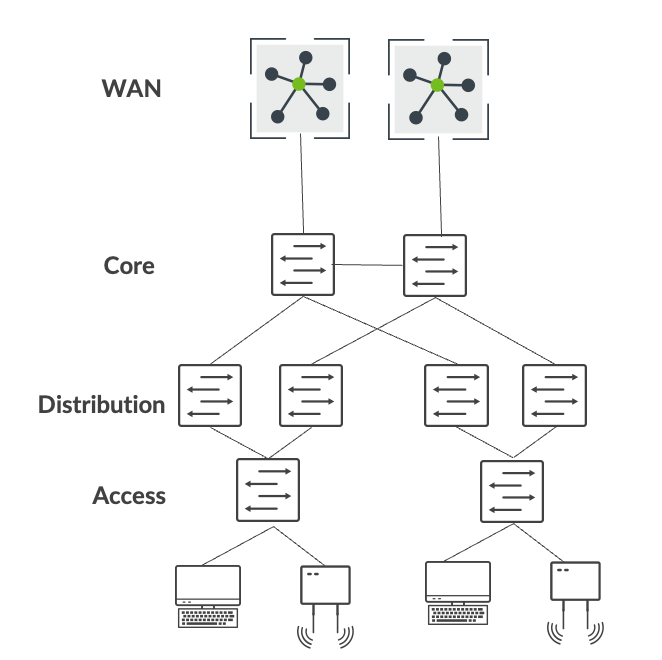
This migration strategy focuses on an enterprise network consisting of the traditional 3-stage architecture of access, distribution, and core. In this example, core provides layer 3 connectivity to all users, printers, access points (APs), and so on. And the core layer interconnects with dual WAN routers using standards based OSPF or BGP technologies.
At a high-level, migration from a traditional enterprise network to a Juniper campus fabric architecture involves the following steps:
- Build a campus fabric architecture in parallel to the existing enterprise network.
- Interconnect the campus fabric to the existing network using a services block.
- Migrate VLANs one by one to the campus fabric.
- Migrate the critical infrastructure such as DHCP server and RADIUS to the services block.
- Migrate WAN router(s) to the services block.
- Decommission the existing enterprise network once all the connectivity is verified.
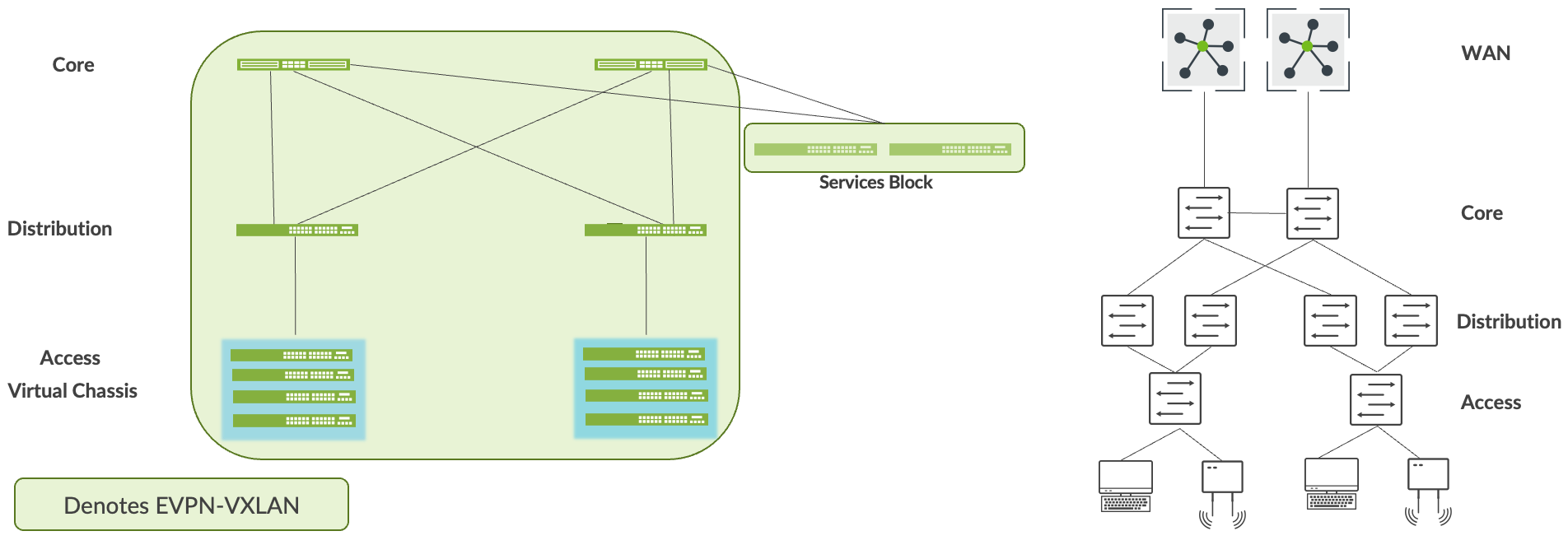
Build Campus Fabric in Parallel to the Existing Network
As the first step, build a campus fabric by using Mist’s Wired Assurance framework. This step allows you to deploy an operational campus fabric in parallel to the existing network. In this example, we choose the campus fabric IP Clos architecture because the customer has a micro-segmentation strategy deployed at the access layer. The customer has chosen the following Juniper equipment to be deployed within the Campus Fabric IP Clos architecture:
- QFX5120 switches (core layer)
- QFX5120 switches (distribution layer)
- EX4100 and EX4400 switches in Virtual Chassis mode (access layer)
- QFX5120 switches (services block)
See also: Configure Campus Fabric IP Clos.
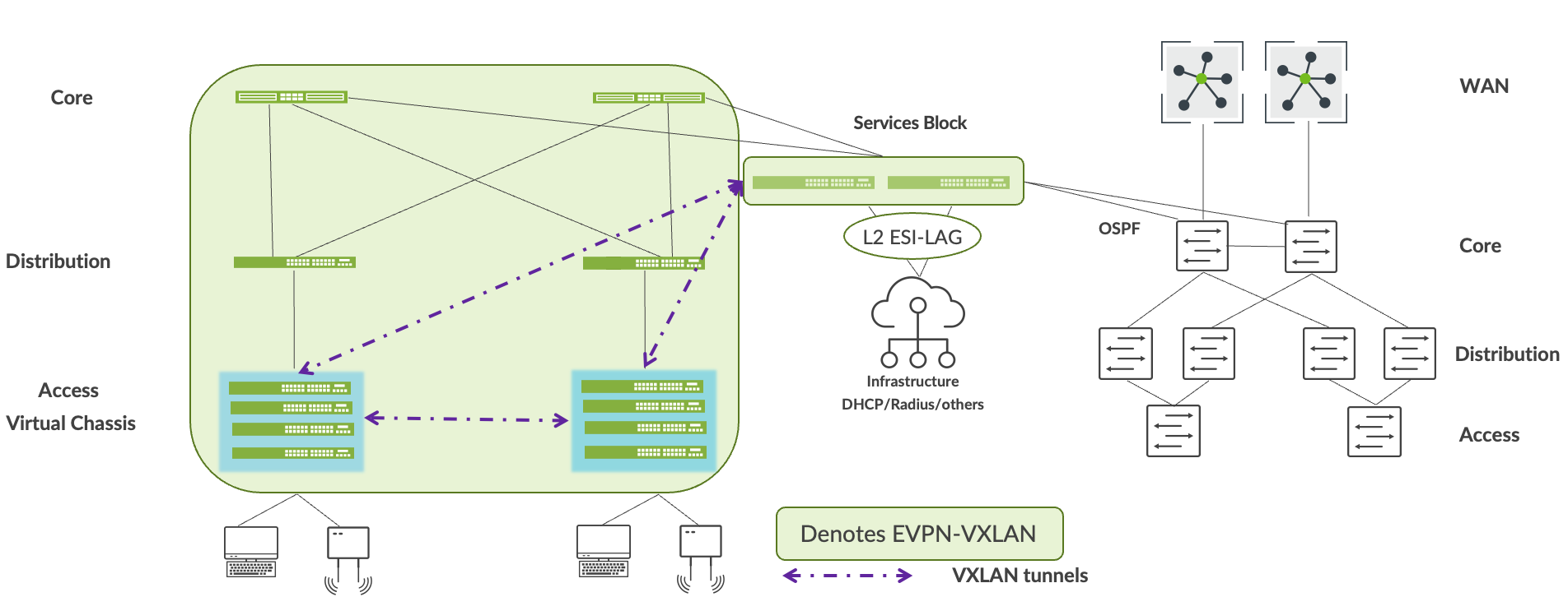
Interconnect the Campus Fabric to the Existing Network
You can use the services block to interconnect the campus fabric with the enterprise network. You can do this by using ESI-LAG technologies at layer 2, or the standard routing protocols such as BGP or OSPF if layer 3 connectivity is required. In this case, we interconnect the services block to the core enterprise using OSPF.
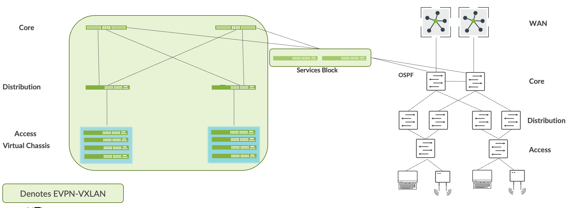
The loopback reachability between the two networks should be established through the services block. For example, the campus fabric build assigns loopback addresses to each device. By default, these addresses are part of the same subnet. OSPF should exchange these addresses with routable prefixes sent by the core layer through the services block. The end-user should verify reachability between these prefixes before moving to the next step.
Migrate VLANs to the Campus Fabric
This process requires you to remove each VLAN and associated layer 3 interface from the enterprise network. You need to migrate all devices within the VLAN to the campus fabric and then have the end-user verify full connectivity from the devices on the migrated VLAN to the applications and devices on the enterprise network. The following summarizes this step:
- Migrate VLANs to campus fabric by disabling or removing the layer 3 subnet from the current network.
- Users and devices migrate to the access layer of the campus fabric.
- Layer 3 interconnect provides reachability on a VLAN-by-VLAN basis.
- Users and devices must validate all application reachability before moving to the next VLAN.
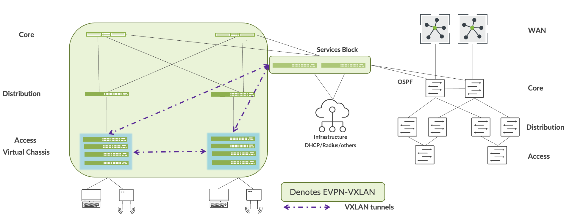
Migrate the Critical Infrastructure to the Services Block
Juniper recommends dual homing of each critical infrastructure service (such as DHCP server and RADIUS) to the services block. You can do this by using ESI-LAG technologies at layer 2, or the standard routing protocols such as BGP or OSPF if layer 3 connectivity is required. Accessibility of critical infrastructure services within the campus fabric and from the enterprise network should be verified before moving to the next step.
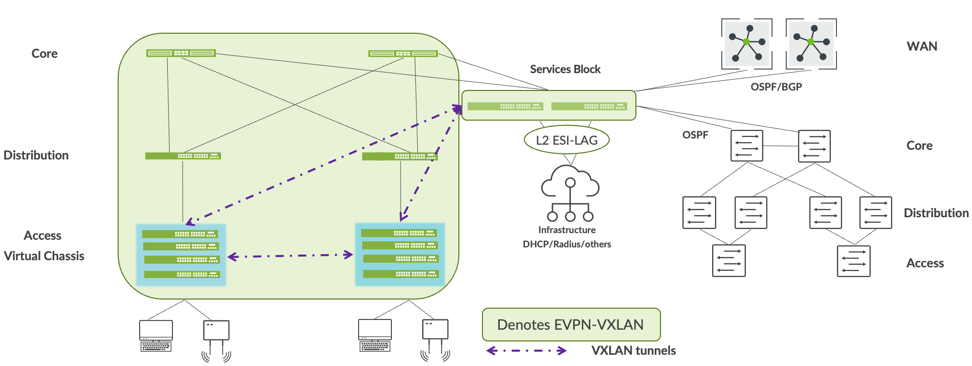
Migrate WAN Router(s) to the Services Block
Mist lets you connect WAN router(s) to the services block using BGP or OSFP. After WAN routers are connected to the services block, verify the accessibility of WAN services to and from the campus fabric before moving to the next step.
Decommission the Existing Enterprise Network
We recommend that you keep the enterprise network up and operational for at least one week after all services and applications are reachable without issue to and from the campus fabric. After that, decommission the existing enterprise network.