Help us improve your experience.

Let us know what you think.

Do you have time for a two-minute survey?


Configure a Custom Rule in Paragon Automation GUI

Create a New Rule Using the Paragon Automation GUI

To create a new rule using the Paragon Automation GUI, you’ll first fill general descriptive information about the rule and then navigate through several rule definition blocks in the Rules page to provide the specific configuration for the Paragon Automation rule.

To start creating a new Paragon Automation rule:

  1. Click the Configuration > Rules icon in the left-navigation bar. A list of Paragon Automation rules is displayed along the left side of the Rules page.
  2. Click the add rule button (+ Add Rule).
  3. Enter general descriptive information about the rule using the following input parameters:

    Parameter

    Description

    Rule

    For a new rule, this parameter is pre-populated with external / user_rule_random characters, for example, external / user_rule_2p0ghk. The fields separated by the slash (/) represent Paragon Automation topic name and Paragon Automation rule name, respectively.

    external is the topic name used for user-defined topics. For the Paragon Automation rules pre-defined by Juniper, Juniper has curated a set of pre-defined device component-based topic names. For more information about Paragon Automation topics, see Understand Paragon Insights Topics.

    Replace the user_rule_random characters rule name with a name that appropriately represents the rule’s description such as packets-in, packets-out, system_memory, etc.

    Rule frequency

    (Network rule only) Specify how often data for the network rule is collected by Paragon Automation . This setting is overridden if the rule is included in a frequency profile that is applied to a network group.

    Description

    (Optional) Enter a detailed description for the rule.

    Synopsis

    (Optional) Enter a brief description for the rule. The synopsis is displayed when you hover over the rule name listed along the left side of the Rules page.

    Field Aggregation Time Range

    This optional value defines how often Paragon Automation aggregates the data received by the sensor. This helps reduce the number of data point entries in the time series database.

  4. (Network rule only) If the new rule is a network rule, toggle the Network rule switch to the right.
  5. Configure the rule definition blocks as needed.

    Located directly below the Synopsis input parameter, you’ll find links to the following rule definition blocks: Sensors, Fields, Vectors, Variables, Functions, Triggers, and Rule Properties. The following sections describe the input parameters for each of these rule definition blocks.

  6. Select one of the following options to save the new rule:

    Save

    Save the rule within the defined topic area but do not deploy the updated configuration. You can use this option when, for example, you are making several changes and want to deploy all your updates at the same time.

    Save & Deploy

    Immediately deploy the configuration and save the rule within the defined topic area.

Rule Filtering

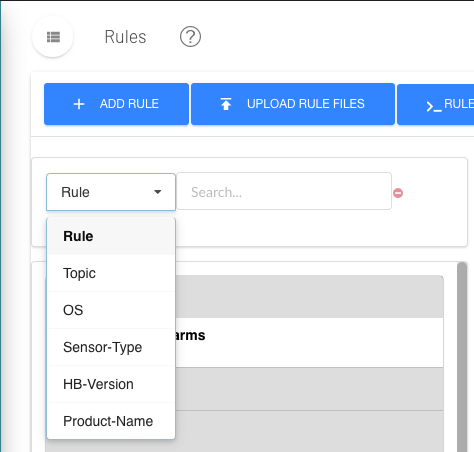
You can filter the Topics and Rules displayed on the left side of the Rules page. This allows you to quickly find rules that you are looking for. The search function works for topics, rules, sensor-types and other categories; working not only on titles, but also on the defined contents of rules.

The following procedure explains this filtering feature.

  1. Navigate to Configuration > Rules in the left-navigation bar.

    The Rules page is displayed. To the left of the rule definition area is a new section as shown in Figure 1 below.

    Figure 1: Rule FilteringRule Filtering
  2. From the pull-down menu, select the type of search you want to perform.
  3. In the search field, begin entering your search text.

    The topic list below shrinks to display only topics and rules that match your search criteria.

Sensors

Start configuring the new rule using the Sensor block. Figure 2 shows the sensor definition for the OpenConfig sensor pppoe-error-statistics.
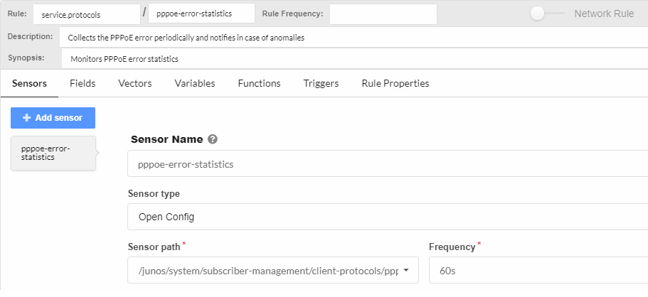
Figure 2: A Sensor DefinitionA Sensor Definition
  1. Click the add sensor button (+ Add Sensor).

    A new sensor definition appears and is named Sensor_random characters, like Sensor_2kgf04.

    You can configure more than one sensor for a rule.

  2. Change the sensor name to something that makes sense for the rule you are defining.
  3. From the drop-down list, choose the sensor type. You can choose one of: OpenConfig, Native GPB, iAgent, SNMP, Syslog, or NetFlow.

    The required elements for defining the Sensor Type change depending on the selection you make. The frequency is expressed in #s, #m, #h, #d, #w, #y, or #o where # is a number and s, m, h, d, w, y specifies seconds, minutes, hours, days, weeks, years, and offset respectively. The o expression is used for defining an offset multiplier for use in formulas, references, triggers, learning periods, and hold-times.

    The following list describes the elements that change based on your choice of Sensor Type. None of the other rule elements change because of a Sensor Type selection.

    • OpenConfig

      Sensor path is defined from a drop-down list of available OpenConfig sensors. Frequency refers to how often, in seconds, the sensor reports to Paragon Automation . The frequency can be overridden if the sensor is included in a frequency profile.

    • Native GPB

      Sensor path refers to the path for a Native GPB sensor. Port refers to the GPB port over which the sensor communicates with Paragon Automation .

    • iAgent

      File is the name of a YAML-formatted file that defines the NETCONF-accessible sensor. Table is defined from a drop-down list of available PyEZ tables and views in the YAML file. Frequency refers to how often the sensor is polled by Paragon Automation and can be overridden by including the sensor in a frequency profile.

      Based on the table you’ve selected, input fields for a target or dynamic arguments might also be provided. For these additional fields, you can do one of the following:

      • Leave the input field blank. No default value will be applied.

      • Enter a fixed value that will remain constant.

      • Enter a variable name enclosed in double curly/flower brackets (for example, {{test-variable}}) The variable name must belong to a variable that was previously defined in the Paragon Automation rule, and the variable’s Type option must be set to Sensor Argument.

    • SNMP

      Table is defined from a drop-down list of available SNMP tables. Frequency refers to how often, in seconds, Paragon Automation polls the device for data and can be overridden by including the sensor in a frequency profile.

    • Syslog

      Pattern set is a user-configured element that includes one or more patterns (you configure a pattern for each event you want to monitor). The Maximum hold period is used in advanced cases and refers to the maximum time that the system will wait when correlating events using multiple patterns within a pattern set.

      Note:

      The syslog sensor requires some pre-configuration. See Syslog Ingest for more details.

    • Flow

      Template Name is a Juniper-supplied built-in list of NetFlow v9 and IPFIX templates.

Fields

A sensor will generally carry information such as all information about interfaces on the device, chassis related information, system process and memory related information, and so on. After you configure sensors, you must mention Fields that process sensor information for a particular need. For example, you can define fields to capture administrative or operational status of an interface or set traffic count threshold.

To add a field:

  1. Click the Fields link.

    The screen updates and shows the defined field objects.

  2. Click the add field button (+ Add Field).
  3. Replace the random field name with a name that make sense for the rule you are defining, such as interface-name, configured-threshold, etc.
  4. (Optional) Add descriptive text for the new field.
  5. Set the appropriate Field Type. The options for field type are: string, integer, float, and unsigned integer. String is the default field type.

    You can also select unsigned integer as a field type. An unsigned integer is a data type that can contain values from 0 through 4,294,967,295.

  6. (Optional) Toggle the Add to rule key switch.

    The add rule to key switch tells Paragon Automation that this field should be indexed and searchable. For example, when you enable this switch, the field name will be listed on the Devices page under the Keys column.

  7. Select the appropriate ingest type (Field source) from the pull-down menu.

    The following list shows the options available for the Ingest type (Field source) menu.

    • Sensor–Use this or another sensor definition.

      • Path-Follow this Open Config or Netconf path within the sensor definition to gather specific data like the names of the interfaces. For iAgent sensors the Path refers to the path defined in the YAML file.

      • Where–Filter the available data to gather information about a specific element within, like a specific interface. This field can reference the Variables defined elsewhere within the rule. When referencing variables, use moustache notation, enclosed in slashes, such as: {{interface_name}}.

      • Zero suppression-For some sensors associated with devices running Junos OS, such as Junos Telemetry Interface Open Config and native GPB sensors, no field data is sent from the sensor when the data’s value is zero. Enable the zero suppression switch to set the field data value to zero whenever no field data is sent from the sensor.

      • Data if missing-Specify a value as the default data value whenever no data is sent from the sensor. The format of the specified value should match the defined field type (string, integer, or float). If the zero suppression switch is also enabled, then the specified data-if-missing value is ignored, and the default sensor data value is set to zero.

    • Reference–A reference to a field or trigger value from another rule.

      • Data if missing-Specify a value as the default data value whenever no reference data is fetched. The format of the specified value should match the defined field type (string, integer, or float).

    • Constant–Use a constant when referring to a Variable defined within the rule, whose value doesn’t change, such as IO_Drops_Threshold A constant can also be a string or numeric value that does not change and is not a reference to a variable.

      • Constant value–Use moustache notation to reference the variable like this: {{IO_Drops_Threshold}}.

    • Formula–Select the desired mathematical formula from the Formula pull-down menu.

  8. (Optional) Set the Field aggregation time-range. Located above the Fields tab with the general rule parameters, this periodic aggregation setting helps to reduce the number of data points entered in the database. For example, if the sensor settings specify that Paragon Automation ingests data every 10 seconds, you could configure this setting to aggregate and record the relevant field data, say, every 60 seconds. Note that when using this setting, any field-specific time ranges must use the same value.
Note:

You can add fields and keys to rules based on whether the incoming data meets user-defined conditions defined in tagging profiles. Tagging profiles are defined in Paragon Automation under Administration > Ingest Settings on the left navigation bar. SeeParagon Insights Tagging for details.

Vectors

(Optional) Now that you have a sensor and fields defined for your rule, you can define vectors.

A vector is used when a single field has multiple values or when you receive a value from another field.

The syntax of a vector is:

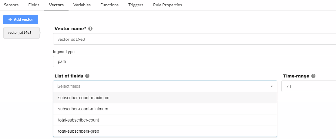
  1. Click on the Vectors link.Figure 3 shows the Vectors block for a newly added vector.
    Figure 3: Vectors BlockVectors Block
  2. Click the add vector button (+ Add Vector)
  3. Replace the random vector name with a name that makes sense for your rule.
  4. Select an ingest type from the drop-down list. The additional input fields will vary depending on the selection you make.

    For path:

    Parameter

    Description

    List of fields

    Select a field from the drop-down list. The list of fields is derived from all of the defined fields in this rule.

    Time-range

    Specify a time range from which the data should be collected. The time range is expressed in #s, #m, #h, #d, #w, #y where # is a number and s, m, h, d, w, y specifies seconds, minutes, hours, days, weeks, and years respectively. For example, enter 7 days as 7d.

    For formula:

    Parameter

    Description

    Vector name

    (Unique formula type only) Select a vector name from the drop-down list. The list of vectors is derived from all of the defined vectors in this rule.

    Formula Type

    Select a formula type from the drop-down list:

    unique

    Creates a vector with unique elements from another vector.

    and

    Compares two vectors and returns a vector with elements common to both vectors.

    or

    Compares two vectors and returns a vector with elements from both vectors.

    unless

    Compares two vectors and returns a vector with elements from the left vector but not the right vector.

    Left vector

    Select a vector name from the drop-down list. The list of vectors is derived from all of the defined vectors in this rule.

    Right vector

    Select a vector name from the drop-down list. The list of vectors is derived from all of the defined vectors in this rule.

Variables

(Optional) The Variables block is where you define the parts of the sensor that you are interested in. For example, a rule that monitors interface throughput needs to have a way to identify specific interfaces from the list of available interfaces on a device. The field details are discussed below.

  1. Click on the Variables tab.
  2. Click the add variable button (+ Add Variable)
  3. Replace the random Variable name with a variable name that makes sense for your rule, such as pem-power-usage-threshold.
    Best Practice:

    The accepted convention within Juniper for naming of elements within Paragon Automation is to always start with a lower-case letter and use hyphens to separate words. Make sure that your variable names are unique, clearly named, and follow a recognizable pattern so that others can understand what the variable is for. Any abbreviations should be used consistently throughout.

  4. Set an appropriate default value in the Default value field.

    Default values vary depending on field type. Integer field types use numeric default values, while string field types use strings to set exact defaults and regular expressions that allow you to set the default from a list. Any default values set during rule definition can be overridden at apply-time at either the device or device group level.

  5. Select the appropriate variable type from the Type drop-down list.

    Available field types are: Integer, Floating Point, String, Boolean, Device, Device Group, and Unsigned Integer.

    You can also select unsigned integer as a variable type. An unsigned integer is a data type that can contain values from 0 through 4,294,967,295.

Functions

(Optional) Define any needed functions.

The Functions block allows users to create functions in a python file and reference the methods that are available in that file. The python file must be created outside of Paragon Automation. You must know about the method names and any arguments because you will need those when defining the functions.

In Paragon Automation, you can use a Python user-defined function to return multiple values. The values are stored in multiple fields in the database.

For example, consider that you have a function example_function.py that has three return values. When you call the example_function.py in a rule, the first return value in the user-defined functions (UDF) is stored in the rule field that calls the function. You only need to configure return fields, such as r2 and r3, for the remaining two return values. You can configure these fields for return values in the Return List of the Functions tab.

In the time-series database, the name of Return List fields are prefixed with the name of the rule field that uses the UDF. For example, rule_field_name-r2.

Figure 4 shows an example configuration in the Functions block.
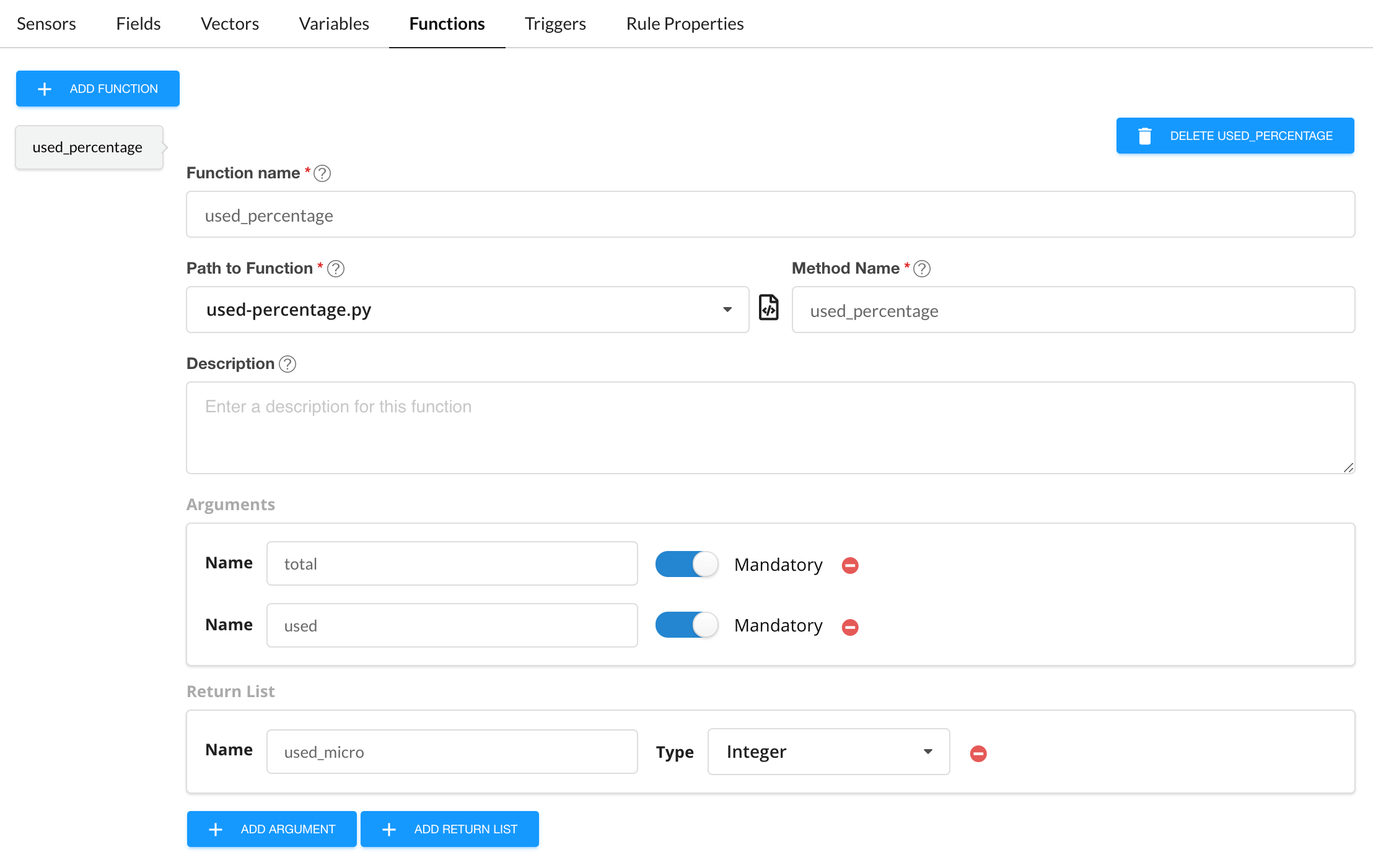
Figure 4: The Functions Block The Functions Block

To configure a function:

  1. Click on the Functions link.
  2. Click + Add Function.
  3. Enter a function name. For example, used-percentage.
  4. In the Path to function field, enter the name of the python file that contains the functions. These files must be stored in the /var/local/healthbot/input/hb-default directory. The list is populated with all the Python (.py) files in that directory.
  5. In the Method Name field, enter the name of the method as defined in the python file. For example, used_percentage.
  6. (Optional) Enter a description for the function in the description box.
  7. (Optional) For each argument that the python function can take, click + Add Argument.

    Each time you click the add argument button, you’ll need to enter the name of the argument and set the toggle switch as to whether the argument is mandatory or not. The default is that none of the arguments are mandatory.

  8. (Optional) If there are more than one argument with a return value in the function, click +Add Return List.
  9. Enter a name for the return value and the data type, such as an integer.

Triggers

A required element of rule definition that you’ll need to set is the trigger element. Figure 5 shows the Triggers block for the system.memory/check-system-memory rule. The field details are discussed below.
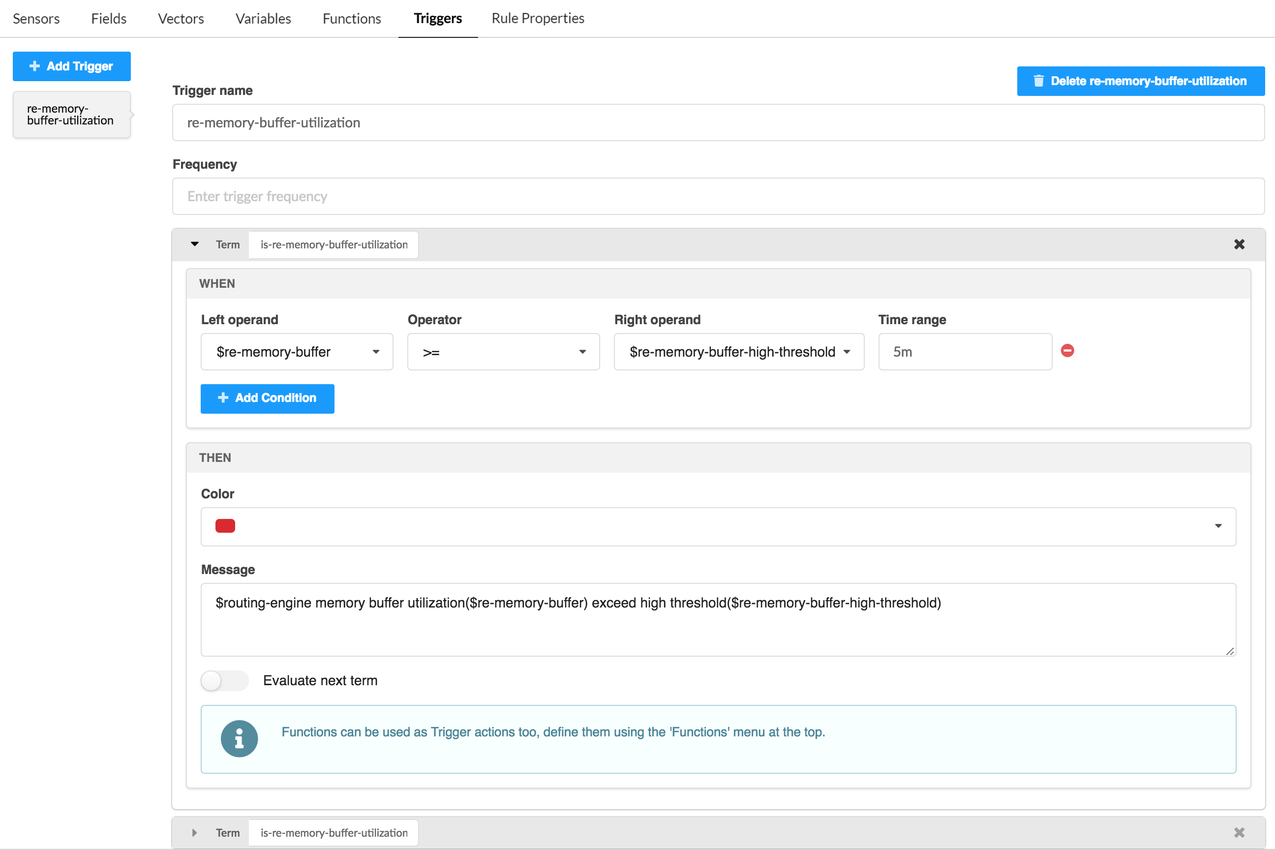
Figure 5: The Triggers BlockThe Triggers Block

Setting up triggers involves creating terms that are used to set policy. If the terms within a trigger are matched, then some action is taken. Terms can evaluate the fields, functions, variables, etc that are defined within the rule against each other or in search of specific values. Terms are evaluated in order from the top of the term list to the bottom. If no match is found, then the next term (if any) is evaluated until a match is found or until the bottom of the term stack is reached.

  1. Click on the Triggers link.
  2. Click on the add trigger button (+ Add Trigger).
  3. Replace the random trigger name with one that makes sense for the trigger you are defining, such as foo-link-operation-state. We recommend using a name that is very unique to the rule and trigger to avoid having the same trigger name across two or more rules.
  4. (Optional) Enter a value in the Frequency field. This value tells Paragon Automation how often the field data and triggers should be queried and evaluated. If no entry is made here, then the sensor frequency is applied for this value. The frequency entered here can be entered as a multiple or, an offset, of the sensor frequency such as 2o. For example, if the sensor frequency is 10s and the trigger frequency is 2o, then the trigger frequency would be 20s (2*10s).
  5. Click the add term button (+ Add Term).

    The Term area will expand and show an add condition button, (+ Add Condition) in the When section and Color and Message fields in the Then section.

  6. To define a condition that the term will evaluate, click the + Add Condition button.

    The When section expands to show Left operand, Operator, and Time range fields.

    Note:

    Setting a condition is not required. If you want to guarantee that a Term takes a specific action, don’t set a condition. This could be useful, for example, at the bottom of a term stack if you want some indication that none of the terms in your trigger matched.

  7. Select values from the pull-down menus for each of these fields.

    Depending on which Operator is chosen, a new field, Right operand may appear in between the Operator and Time range fields.

    The left and right operand pull-down menus are populated with the fields and variables defined in the rule. The operator field determines what kind of comparison is done. The time range field allows the trigger to evaluate things such as if there were any dropped packets in the last minute.

  8. (Optional) Set values for the Color and Message fields, and add Action Engine information in the Then section.

    These fields are the action fields. If a match is made in the condition set within the same term, then whatever action you define here is taken. A color value of green, yellow, or red can be set. A message can also be set and is not dependent on whether any color is set.

    You can link action workflows (Action Engine) to rules while setting up triggers. You can also add input arguments while linking action workflows. The Action Engine section is enabled only with a PIN-Advanced license. For more information, see Action Engine Workflow Overview and Paragon Insights Licensing Overview.

    If color or message are set, a toggle button labeled Evaluate next term appears at the bottom of the Then section. The default value for this button is off (not active).

    Note:

    If no match is made in the When section of a term, the Then section is ignored. If this happens, the next term down, if any, is evaluated.

    If a match is made in the When section, then the actions in the Then section, if any, are taken and processing of terms stops unless the Evaluate next term button is set to on (active).

    Setting the Evaluate next term button allows you to have Paragon Automation make more complex evaluations like ’if one condition and another condition are both true, then take this action’.

Rule Properties

(Optional) Specify metadata for your Paragon Automation rule in the Rule Properties block. Available options include:

Attributes

Description

Version

Enter the version of the Paragon Automation rule.

Contributor

Choose an option from the drop-down list.

Author

Specify a valid e-mail address.

Date

Choose a date from the pop-up calendar.

Supported Paragon Automation Version

Specify the earliest Paragon Automation release for which the rule is valid.

Supported Device > Juniper Devices

Choose either Junos or Junos Evolved. Device metadata includes Product Name, Release Name, Release Support (drop-down list), and platform. You can add metadata for multiple devices, multiple products per device, and multiple releases per product.

You can select default sensors that you want to apply to all supported devices. You also have the option to select default sensors that you want to apply to Juniper devices, and to Juniper devices that run a specific OS.

Supported Device > Other Vendor Devices

You can add vendor identifier, vendor name, product, platform, release, and operating system-related information for non-Juniper vendors.

You can select default sensors that you want to apply to all non-Juniper devices.

Helper Files

Specify files that are required by the Paragon Automation rule.

Pre-Action Tasks

Before you configure the pre-action tasks in rules, you must configure Action Engine workflows. See Manage Action Engine Workflows to configure Action Engine workflows.

To configure pre-action task:

  1. Click the Pre/Post Actions tab on the Rules page.

  2. In the Pre-Action section, select an action engine workflow in the Action Engine list.

  3. Enter the input argument from the device list.

    The list shows arguments you previously configured in the selected action engine workflow as the pre-action task.

  4. Enable execute-once if you want Paragon Automation to execute the pre-action task only once on each device in a device group.

  5. Do one of the following:

    • Click Save to save your configuration changes but do not deploy the updated configuration. You can use this option when, for example, you are making several changes and want to deploy all your updates at the same time later.

      See Commit or Roll Back Configuration Changes in Paragon Insights for more information.

    • Click Save and Deploy to save the rule configuration in the GUI and deploy the configuration.

      When you include the rule in a playbook and run a playbook instance on a device group, Paragon Automation executes the pre-action task while ingesting telemetry data.

You can monitor the status of the Action Engine Workflow embedded within a pre-action tab. See Manage Action Engine Workflows for more information.

Post-Action Tasks

Before you configure the post-action tasks in rules, you must configure Action Engine workflows. See Manage Action Engine Workflows to configure Action Engine workflows.

To configure post-action tasks:

  1. Click the Pre/Post Actions tab on the Rules page.

  2. In the Post-Action section, select an action engine workflow in the Action Engine list.

  3. Enter the input argument from the device list.

    The list shows arguments you previously configured in the selected action engine workflow as the post-action task.

  4. Enable execute-once if you want Paragon Automation to execute the post-action task only once on each device in a device group.

  5. Do one of the following:

    • Click Save to save your configuration changes but do not deploy the updated configuration. You can use this option when, for example, you are making several changes and want to deploy all your updates at the same time later.

      See Commit or Roll Back Configuration Changes in Paragon Insights for more information.

    • Click Save and Deploy to save the rule configuration in the GUI and deploy the configuration.

      When you stop the playbook instance (with this rule), Paragon Automation executes the post-action task after it stops the service for playbooks.

You can monitor the status of the Action Engine Workflow embedded within a post-action tab. See Manage Action Engine Workflows for more information.