ON THIS PAGE
Example: Configure an Egress Single-Rate Two-Color Policer and Multifield Classifiers
This example shows how to limit customer traffic within your network using a single-rate two-color policer. Policers use a concept known as a token bucket to identify which traffic to drop. The policer enforces the CoS strategy of in-contract and out-of-contract traffic at the interface level. You can apply a single-rate two-color policer to incoming packets, outgoing packets, or both. This example applies the policer as an output (egress) policer for outgoing traffic. The multifield classifier CoS queueing option places the traffic into the assigned queues which will help you manage resource utilization at the output interface level by applying scheduling and shaping later.
A thorough explanation of the token bucket concept and its underlying algorithms is beyond the scope of this document. For more information about traffic policing, and CoS in general, refer to QOS-Enabled Networks—Tools and Foundations by Miguel Barreiros and Peter Lundqvist. This book is available at many online booksellers and at www.juniper.net/books.
Requirements
To verify this procedure, this example uses a traffic generator. The traffic generator can be hardware-based or it can be software running on a server or host machine.
The functionality in this procedure is widely supported on devices that run Junos. The example shown here was tested and verified on MX Series routers running a supported Junos OS release.
Overview
Policing
Single-rate two-color policing enforces a configured rate of traffic flow for a particular service level by applying implicit or configured actions to traffic that does not conform to the limits. When you apply a single-rate two-color policer to the input or output traffic at an interface, the policer meters the traffic flow to the rate limit defined by the following components:
-
Bandwidth limit—The average number of bits per second permitted for packets received or transmitted at the interface. You can specify the bandwidth limit as an absolute number of bits per second or as a percentage value from 1 through 100. If a percentage value is specified, the effective bandwidth limit is calculated as a percentage of either the physical interface media rate or the logical interface configured shaping rate.
-
Burst-size limit—The maximum size permitted for bursts of data. Burst sizes are measured in bytes. We recommend two formulas for calculating burst size:
Burst size = bandwidth x allowable time for burst traffic / 8
Or
Burst size = interface mtu x 10
For information about configuring the burst size, see Determining Proper Burst Size for Traffic Policers.
Note:There is a finite buffer space for an interface. In general, the estimated total buffer depth for an interface is about 125 ms.
For a traffic flow that conforms to the configured limits (categorized
as green traffic), packets are implicitly marked with a packet loss
priority (PLP) level of low and are allowed to pass through
the interface unrestricted.
For a traffic flow that exceeds the configured limits (categorized as red traffic), packets are handled according to the traffic-policing actions configured for the policer. This example discards packets that burst over the 15 KBps limit.
To rate-limit Layer 3 traffic, you can apply a two-color policer in the following ways:
-
Directly to a logical interface, at a specific protocol level.
-
As the action of a standard stateless firewall filter that is applied to a logical interface, at a specific protocol level. This is the technique used in this example.
To rate-limit Layer 2 traffic, you can apply a two-color policer as a logical interface policer only. You cannot apply a two-color policer to Layer 2 traffic through a firewall filter.
You can choose either bandwidth-limit or bandwidth percent within the policer, as they are mutually exclusive. You cannot configure a policer to use bandwidth percent for aggregate, tunnel, and software interfaces.
In this example, as illustrated in Figure 1, Host1 connected to device R1 and Host3 connected to device R3 are traffic generators emulating webservers. Both Host1 and Host3 are sending traffic to Host2 behind device R2. Devices R1, R2, and R3 are owned by a service provider. Host1 is accessed by users on Host2 behind R2. Host1 and Host2 are owned by the same customer and their traffic must be managed. Host1 will be sending traffic with a source TCP HTTP port of 80 to the users. A single-rate two-color policer is configured and applied to the interface on R1 that connects to R2. The policer enforces the contract agreed upon by the webserver owner and the service provider for the bandwidth available to the web traffic flowing between R1 and R2.
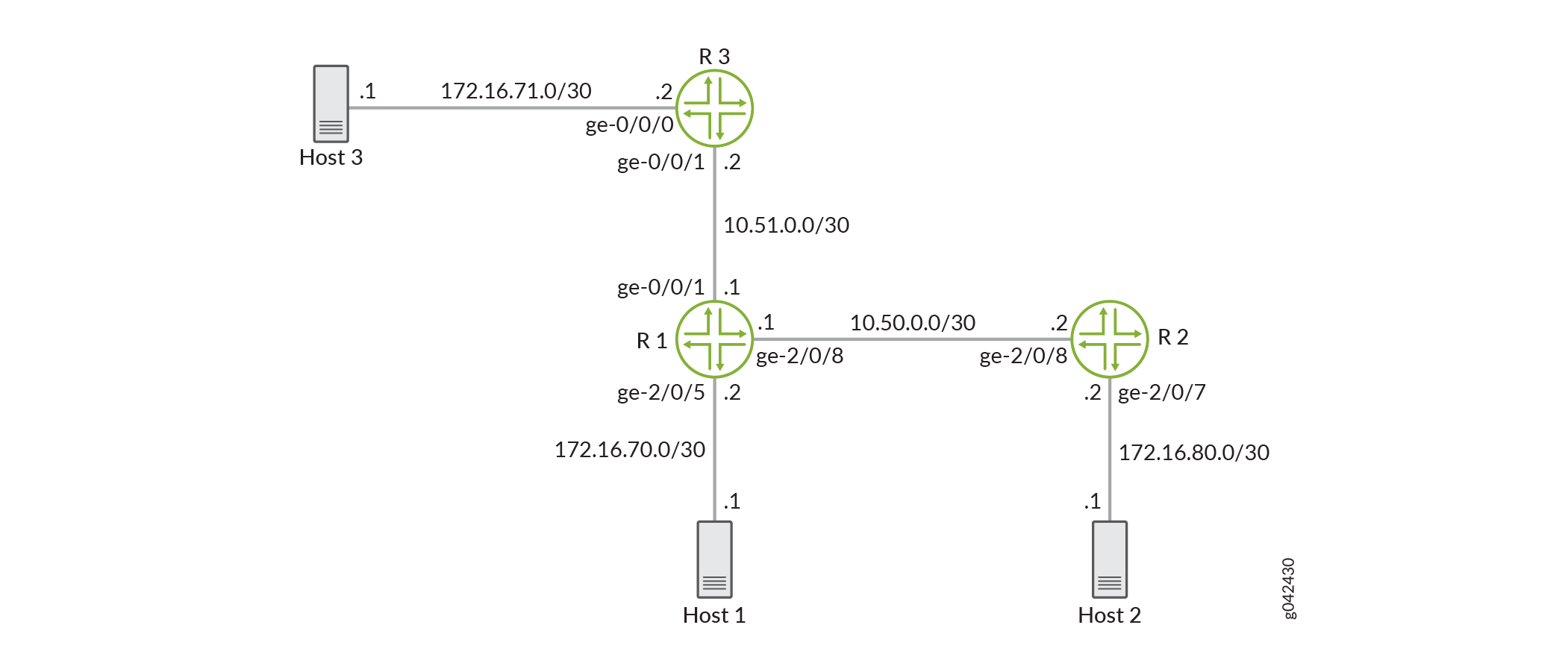
This example applies an egress policer between R1 and R2 because this is the point where the traffic from both customer sites shares the same link. This makes it easier to enforce the required policing parameters. Trying to rate-limit the combined customer traffic on the link between R1 and R2 by applying the policers as ingress policers on interfaces ge-0/0/0 on R3 and ge-2/0/5 on R1 would be complicated because using the contracted rate of 700 Mbps (70 percent) of the available bandwidth with an allowable burst rate of 10 x the MTU size of the gigabit Ethernet interface between Host3 and R3 and the Host1 and R1 would result in allowing a maximum throughput of 1400 Mbps over the link between R1 and R2.
Therefore, the rate-limiting applied to the host connections between the hosts and R3 and R1 would have to be reduced below 700 Mbps. The calculation of what to reduce the rate-limit number to would be a problem because just reducing each host to 350 Mbps would mean that if one host was transmitting traffic while the other host was not transmitting, the maximum throughput on the link between R1 and R2 would be only one half of the contracted rate (350 Mbps instead of 700 Mbps). This is why this example is useful to show the amount of thought that must go into applying CoS in a network to achieve the desired goals.
According to the contractual bandwidth availability, the egress policer on R1 will limit the HTTP port 80 traffic originating from Host1 to using 700 Mbps (70 percent) of the available bandwidth with an allowable burst rate of 10 x the MTU size of the gigabit Ethernet interface between R1 and R2.
Additional traffic from TCP source port 12345 is used in this example to further illustrate how traffic is allocated to the outbound queues.
In a real-world scenario you would probably also rate-limit traffic for a variety of other ports such as FTP, SFTP, SSH, TELNET, SMTP, IMAP, and POP3 because they are often included as additional services with web hosting services.
You must leave some additional bandwidth available that is not rate-limited for network control protocols such as routing protocols, DNS, and any other protocols required to keep network connectivity operational. This is why the firewall filter has a final accept condition on it.
Topology
This example uses the topology in Figure 2.
Figure 3 shows the policing behavior.
Multifield Classifying
A classifier is a software operation that a router or switch uses to inspect and classify a packet after it has made it through any policing, if policing is configured. During classification, the packet header contents are examined, and this examination determines how the packet is treated when the outbound interface becomes too busy to handle all of the packets and you want your device to drop packets intelligently, instead of dropping packets indiscriminately. One common way to detect packets of interest is by source port number. The TCP source port numbers 80 and 12345 are used in this example, but many other matching criteria for packet detection are available to multifield classifiers, using firewall filter match conditions. The configuration in this example specifies that TCP packets with a source port 80 are classified into the BE-data forwarding class and queue number 0, and TCP packets with a source port 12345 are classified into the Premium-data forwarding class and queue number 1. Traffic from both port numbers is monitored by the policer first. If the traffic makes it through the policer, it is handed off to the outbound interface in the assigned queue for transmission.
Multifield classifiers are typically used at the network edge as packets enter an autonomous system (AS). However, as explained previously in the policing section, in this example the multifield classifier is configured within the AS of the service provider.
In this example, you configure the firewall filter mf-classifier and specify some custom forwarding classes on R1. In specifying the custom forwarding classes, you also associate each class with a queue.
The classifier operation is shown in Figure 4.
You monitor the behavior of the queues on the interfaces that
the traffic is transmitted over. In this example, to determine how
the queues are being serviced, you examine the traffic statistics
on interface ge-2/0/8 on R1 by using the extensive option
in the show interfaces command.
Configuration
Procedure
- CLI Quick Configuration
- Step-by-Step Procedure
- Step-by-Step Procedure
- Step-by-Step Procedure
- Results
CLI Quick Configuration
To quickly configure this example,
copy the following commands, paste them into a text file, remove any
line breaks, change any details necessary to match your network configuration,
and then copy and paste the commands into the CLI at the [edit] hierarchy level.
Device R1
set interfaces ge-0/0/1 description to-R3
set interfaces ge-0/0/1 unit 0 family inet address 10.51.0.1/30
set interfaces ge-2/0/5 description to-Host
set interfaces ge-2/0/5 unit 0 family inet address 172.16.70.2/30
set interfaces ge-2/0/8 description to-R2
set interfaces ge-2/0/8 unit 0 family inet address 10.50.0.1/30
set interfaces ge-2/0/8 unit 0 family inet filter output mf-classifier
set interfaces lo0 unit 0 description loopback-interface
set interfaces lo0 unit 0 family inet address 192.168.13.1/32
set firewall policer discard if-exceeding bandwidth-limit 700m
set firewall policer discard if-exceeding burst-size-limit 15k
set firewall policer discard then discard
set class-of-service forwarding-classes class BE-data queue-num 0
set class-of-service forwarding-classes class Premium-data queue-num 1
set class-of-service forwarding-classes class Voice queue-num 2
set class-of-service forwarding-classes class NC queue-num 3
set firewall family inet filter mf-classifier term BE-data from protocol tcp
set firewall family inet filter mf-classifier term BE-data from port http
set firewall family inet filter mf-classifier term BE-data then forwarding-class BE-data
set firewall family inet filter mf-classifier term BE-data then policer discard
set firewall family inet filter mf-classifier term Premium-data from protocol tcp
set firewall family inet filter mf-classifier term Premium-data from port 12345
set firewall family inet filter mf-classifier term Premium-data then forwarding-class Premium-data
set firewall family inet filter mf-classifier term Premium-data then policer discard
set firewall family inet filter mf-classifier term accept then accept
set protocols ospf area 0.0.0.0 interface ge-2/0/5.0 passive
set protocols ospf area 0.0.0.0 interface lo0.0 passive
set protocols ospf area 0.0.0.0 interface ge-0/0/1.0
set protocols ospf area 0.0.0.0 interface ge-2/0/8.0
Device R2
set interfaces ge-2/0/7 description to-Host
set interfaces ge-2/0/7 unit 0 family inet address 172.16.80.2/30
set interfaces ge-2/0/8 description to-R1
set interfaces ge-2/0/8 unit 0 family inet address 10.50.0.2/30
set interfaces lo0 unit 0 description loopback-interface
set interfaces lo0 unit 0 family inet address 192.168.14.1/32
set protocols ospf area 0.0.0.0 interface ge-2/0/7.0 passive
set protocols ospf area 0.0.0.0 interface lo0.0 passive
set protocols ospf area 0.0.0.0 interface ge-2/0/8.0
Device R3
set interfaces ge-0/0/0 description to-Host
set interfaces ge-0/0/0 unit 0 family inet address 172.16.71.1/30
set interfaces ge-0/0/1 description to-R1
set interfaces ge-0/0/1 unit 0 family inet address 10.51.0.2/30
set interfaces lo0 unit 0 description loopback-interface
set interfaces lo0 unit 0 family inet address 192.168.15.1/32
set protocols ospf area 0.0.0.0 interface ge-0/0/0.0 passive
set protocols ospf area 0.0.0.0 interface lo0.0 passive
set protocols ospf area 0.0.0.0 interface ge-0/0/1.0
Step-by-Step Procedure
The following example requires you to navigate various levels in the configuration hierarchy. For instructions on how to do that, see Using the CLI Editor in Configuration Mode in the Junos OS CLI User Guide.
To configure R1:
-
Configure the device interfaces.
[edit interfaces]
user@R1# set ge-0/0/1 description to-R3
user@R1# set ge-0/0/1 unit 0 family inet address 10.51.0.1/30
user@R1# set ge-2/0/5 description to-Host
user@R1# set ge-2/0/5 unit 0 family inet address 172.16.70.2/30
user@R1# set ge-2/0/8 description to-R2
user@R1# set ge-2/0/8 unit 0 family inet address 10.50.0.1/30
-
Configure the policer to rate-limit to a bandwidth of 700 Mbps and a burst size of 15 KBps.
[edit firewall policer discard]
user@R1# set if-exceeding bandwidth-limit 700m
user@R1# set if-exceeding burst-size-limit 15k
-
Configure the policer to discard packets in the red traffic flow.
[edit firewall policer discard]
user@R1# set then discard
-
Configure the custom forwarding classes and associated queue numbers.
[edit class-of-service forwarding-classes]
user@R1# set class BE-data queue-num 0
user@R1# set class Premium-data queue-num 1
user@R1# set class Voice queue-num 2
user@R1# set class NC queue-num 3
-
Configure the firewall filter term that places TCP traffic with a source port of 80 (HTTP traffic) into the BE-data forwarding class, associated with queue 0.
[edit firewall family inet filter mf-classifier]
user@R1# set term BE-data from protocol tcp
user@R1# set term BE-data from port http
user@R1# set term BE-data then forwarding-class BE-data
user@R1# set term BE-data then policer discard
-
Configure the firewall filter term that places TCP traffic with a source port of 12345 into the Premium-data forwarding class, associated with queue 1.
[edit firewall family inet filter mf-classifier]
user@R1# set term Premium-data from protocol tcp
user@R1# set term Premium-data from port 12345
user@R1# set term Premium-data then forwarding-class Premium-data
user@R1# set term Premium-data then policer discard
-
At the end of your firewall filter, configure a default term that accepts all other traffic.
Otherwise, all traffic that arrives on the interface that is not explicitly accepted by the firewall filter is discarded.
[edit firewall family inet filter mf-classifier]
user@R1# set term accept then accept
-
Apply the firewall filter to interface ge-2/0/8 as an output filter.
[edit interfaces]
user@R1# set ge-2/0/8 unit 0 family inet filter output mf-classifier
-
Configure OSPF.
[edit protocols ospf]
user@R1# set area 0.0.0.0 interface ge-2/0/5.0 passive
user@R1# set area 0.0.0.0 interface lo0.0 passive
user@R1# set area 0.0.0.0 interface ge-0/0/1.0
user@R1# set area 0.0.0.0 interface ge-2/0/8.0
Step-by-Step Procedure
To configure R2:
-
Configure the device interfaces.
[edit]
user@R2# set interfaces ge-2/0/7 description to-Host
user@R2# set interfaces ge-2/0/7 unit 0 family inet address 172.16.80.2/30
user@R2# set interfaces ge-2/0/8 description to-R1
user@R2# set interfaces ge-2/0/8 unit 0 family inet address 10.50.0.2/30
user@R2# set interfaces lo0 unit 0 description loopback-interface
user@R2# set interfaces lo0 unit 0 family inet address 192.168.14.1/32
Configure OSPF.
[edit protocols ospf]
user@R2# set area 0.0.0.0 interface ge-2/0/7.0 passive
user@R2# set area 0.0.0.0 interface lo0.0 passive
user@R2# set area 0.0.0.0 interface ge-2/0/8.0
Step-by-Step Procedure
To configure R3:
-
Configure the interfaces.
[edit]
user@R3# set interfaces ge-0/0/0 description to-Host
user@R3# set interfaces ge-0/0/0 unit 0 family inet address 172.16.71.1/30
user@R3# set interfaces ge-0/0/1 description to-R1
user@R3# set interfaces ge-0/0/1 unit 0 family inet address 10.51.0.2/30
user@R3# set interfaces lo0 unit 0 description loopback-interface
user@R3# set interfaces lo0 unit 0 family inet address 192.168.15.1/32
-
Configure OSPF
[edit protocols ospf]
user@R3# set protocols ospf area 0.0.0.0 interface ge-0/0/0.0 passive
user@R3# set protocols ospf area 0.0.0.0 interface lo0.0 passive
user@R3# set protocols ospf area 0.0.0.0 interface ge-0/0/1.0
Results
From configuration mode, confirm your configuration
by entering the show interfaces, show class-of-service, show firewall, and show protocols ospf commands.
If the output does not display the intended configuration, repeat
the instructions in this example to correct the configuration.
user@R1# show interfaces
ge-0/0/1 {
    description to-R3;
    unit 0 {
        family inet {
            address 10.51.0.1/30;
        }
    }
}
}
    ge-2/0/5 {
        description to-Host;
        unit 0 {
            family inet {
                address 172.16.70.2/30;
            }
        }
    }
    ge-2/0/8 {
        description to-R2;
        unit 0 {
            family inet {
                filter {
                    output mf-classifier;
                }
                address 10.50.0.1/30;
            }
        }
    }
lo0 {
    unit 0 {
        description loopback-interface;
        family inet {
            address 192.168.13.1/32;
        }
    }
}
user@R1# show class-of-service
forwarding-classes {
    class BE-data queue-num 0;
    class Premium-data queue-num 1;
    class Voice queue-num 2;
    class NC queue-num 3;
}
user@R1# show firewall
family inet {
    filter mf-classifier {
        term BE-data {
            from {
                protocol tcp;
                port http;
            }
            then {
                policer discard;
                forwarding-class BE-data;
            }
        }
        term Premium-data {
            from {
                protocol tcp;
                port 12345;
            }
            then {
                policer discard;
                forwarding-class Premium-data;
            }
        }
        term accept {
            then accept;
        }
    }
}
policer discard {
    if-exceeding {
        bandwidth-limit 700m;
        burst-size-limit 15k;
    }
    then discard;
}
user@R1# show protocols ospf
area 0.0.0.0 {
    interface ge-2/0/5.0 {
        passive;
    }
    interface lo0.0 {
        passive;
    }
    interface ge-0/0/1.0;
    interface ge-2/0/8.0;
}
If you are done configuring R1, enter commit from
configuration mode.
user@R2# show interfaces
ge-2/0/7 {
    description to-Host;
    unit 0 {
        family inet {
            address 172.16.80.2/30;
        }
    }
}
ge-2/0/8 {
    description to-R1;
    unit 0 {
        family inet {
            address 10.50.0.2/30;
        }
    }
}
lo0 {
    unit 0 {
        description loopback-interface;
        family inet {
            address 192.168.14.1/32;
        }
    }
}
user@R2# show protocols ospf
area 0.0.0.0 {
    interface ge-2/0/7.0 {
        passive;
    }
    interface lo0.0 {
        passive;
    }
    interface ge-2/0/8.0;
}
If you are done configuring R2, enter commit from
configuration mode.
user@R3# show interfaces
ge-0/0/0 {
    description to-Host;
    unit 0 {
        family inet {
            address 172.16.71.2/30;
        }
    }
}
ge-0/0/1 {
    description to-R1;
    unit 0 {
        family inet {
            address 10.51.0.2/30;
        }
    }
}
lo0 {
    unit 0 {
        description loopback-interface;
        family inet {
            address 192.168.15.1/32;
        }
    }
}
user@R3# show protocols ospf
area 0.0.0.0 {
    interface ge-0/0/0.0 {
        passive;
    }
    interface lo0.0 {
        passive;
    }
    interface ge-0/0/1.0;
}
If you are done configuring R3, enter commit from
configuration mode.
Verification
Confirm that the configuration is working properly.
- Checking the CoS Settings
- Clearing the Counters
- Sending Traffic into the Network from TCP HTTP Port 80 and Monitoring the Results
- Sending Traffic into the Network from TCP Port 12345 and Monitoring the Results
Checking the CoS Settings
Purpose
Confirm that the forwarding classes are configured correctly.
Action
From R1, run the show class-of-service forwarding-class command.
user@R1> show class-of-service forwarding-class

Forwarding class                       ID      Queue  Restricted queue  Fabric priority  Policing priority   SPU priority
  BE-data                               0       0          0             low                normal            low
  Premium-data                          1       1          1             low                normal            low
  Voice                                 2       2          2             low                normal            low
  NC                                    3       3          3             low                normal            low
Meaning
The output shows the configured custom classifier settings.
Clearing the Counters
Purpose
Confirm that the firewall and interface counters are cleared.
Action
-
On R1, run the
clear firewall allcommand to reset the firewall counters to 0.user@R1> clear firewall all
-
On R1, run the
clear interface statistics ge-2/0/5command to reset the interface counters to 0.user@R1> clear interface statistics ge-2/0/8
Sending Traffic into the Network from TCP HTTP Port 80 and Monitoring the Results
Purpose
Send traffic that can monitored at the policer and custom queue level.
Action
-
Use a traffic generator to send 20 TCP packets with a source port of 80 into the network.
The
-sflag sets the source port. The-kflag causes the source port to remain steady at 80 instead of incrementing. The-cflag sets the number of packets to 20. The-dflag sets the packet size.Note:In this example the policer numbers are reduced to a bandwidth limit of 8 Kbps and a burst size limit of 1500 KBps to ensure that some packets are dropped.
[User@host]#  hping 172.16.80.1  -c 20 -s 80  -k -d 300

[User@Host]# hping 172.16.80.1 -s 80 -k -c 20 -d 375
HPING 172.16.80.1 (eth1 172.16.80.1): NO FLAGS are set, 40 headers + 375 data bytes
len=46 ip=172.16.80.1 ttl=62 DF id=0 sport=0 flags=RA seq=0 win=0 rtt=1001.0 ms
.
.
.
--- 172.16.80.1 hping statistic ---
20 packets transmitted, 14 packets received, 30% packet loss
round-trip min/avg/max = 1001.0/10287.1/19002.1 ms
-
On R1, check the firewall counters by using the
show firewallcommand.user@R1> show firewall Filter: mf-classifier Policers: Name Bytes Packets discard-BE-data 2490 6 discard-Premium-data 0 0
Notice that in the
hpingoutput that there was 30% packet loss (6 packets out of 20) and the same number of packets was dropped by the policer as shown in the output of theshow firewallcommand. Also notice that the drops are associated with the queueBE-dataas specified in themf-classifierin the firewall configuration. -
On R1, check the queue counters by using the
show interfaces extensive ge-2/0/8| find "Queue counters"command.user@R1> show interfaces extensive ge-2/0/8| find "Queue counters" Queue counters: Queued packets Transmitted packets Dropped packets 0 14 14 0 1 0 0 0 2 0 0 0 3 16 16 0 Queue number: Mapped forwarding classes 0 BE-data 1 Premium-data 2 Voice 3 NC
Notice that 14 packets were transmitted out interface 2/0/8 using the queue
BE-dataas specified in themf-classifierin the firewall configuration. The remaining 6 packets were dropped by the policer, as shown above. The 16 packets sent to queue 3 are network control traffic. They are possibly routing protocol updates.
Meaning
The output from both devices shows that 6 packets were discarded This means that there was at least 8 Kbps of green (in-contract HTTP port 80) traffic and that the 1500 KBps burst option for red (out-of-contract HTTP port 80) traffic was exceeded. In Steps 2 and 3, you can see that the correct queues were used to transmit the remaining traffic out interface 2/0/8.
Sending Traffic into the Network from TCP Port 12345 and Monitoring the Results
Purpose
Send traffic that can monitored at the policer and custom queue level.
Action
-
Clear the counters again as shown in section Clearing the Counters.
-
Use a traffic generator to send 20 TCP packets with a source port of 12345 into the network.
The
-sflag sets the source port. The-kflag causes the source port to remain steady at 12345 instead of incrementing. The-cflag sets the number of packets to 20. The-dflag sets the packet size.[User@host]# hping 172.16.80.1 -c 20 -s 12345 -k -d 300 [Host@User]# hping 172.16.80.1 -s 12345 -k -c 20 -d 375 HPING 172.16.80.1 (eth1 172.16.80.1): NO FLAGS are set, 40 headers + 375 data bytes len=46 ip=172.16.80.1 ttl=62 DF id=0 sport=0 flags=RA seq=0 win=0 rtt=1000.4 ms . . . --- 172.16.80.1 hping statistic --- 20 packets transmitted, 13 packets received, 35% packet loss round-trip min/avg/max = 1000.4/10924.5/19002.2 ms
-
On R1, check the firewall counters by using the
show firewallcommand.user@R1> show firewall Filter: mf-classifier Policers: Name Bytes Packets discard-BE-data 0 0 discard-Premium-data 2905 7
Notice that in the
hpingoutput that there was 35% packet loss (7 packets out of 20) and the same number of packets were dropped by the policer as shown in the output of theshow firewallcommand. Also notice that the drops are associated with the queuePremium-dataas specified in themf-classifierin the firewall configuration. -
On R1, check the queue counters by using the
show interfaces extensive ge-2/0/8| find "Queue counters"command.user@R1> show interfaces extensive ge-2/0/8| find "Queue counters" Queue counters: Queued packets Transmitted packets Dropped packets 0 0 0 0 1 13 13 0 2 0 0 0 3 16 16 0 Queue number: Mapped forwarding classes 0 BE-data 1 Premium-data 2 Voice 3 NC
Notice that 13 packets were transmitted out interface 2/0/8 using the Premium-data queues specified in the
mf-classifierin the firewall configuration. The remaining 7 packets were dropped by the policer, as shown above. The 16 packets sent to queue 3 are network control traffic. They are possibly routing protocol updates.
Meaning
The output from both devices shows that 7 packets were discarded. This means that there was at least 8 Kbps of green (in-contract HTTP port 80) traffic and that the 1500 KBps burst option for red (out-of-contract HTTP port 80) traffic was exceeded. In Steps 3 and 4, you can see that the correct queues were used to transmit the remaining traffic out interface 2/0/8.