- play_arrow Overview
- play_arrow Understanding How Class of Service Manages Congestion and Defines Traffic Forwarding Behavior
- Understanding How Class of Service Manages Congestion and Controls Service Levels in the Network
- How CoS Applies to Packet Flow Across a Network
- The Junos OS CoS Components Used to Manage Congestion and Control Service Levels
- Mapping CoS Component Inputs to Outputs
- Default Junos OS CoS Settings
- Packet Flow Through the Junos OS CoS Process Overview
- Configuring Basic Packet Flow Through the Junos OS CoS Process
- Example: Classifying All Traffic from a Remote Device by Configuring Fixed Interface-Based Classification
- Interface Types That Do Not Support Junos OS CoS
-
- play_arrow Configuring Platform-Specific Functionality
- play_arrow Configuring Class of Service on ACX Series Universal Metro Routers
- CoS on ACX Series Routers Features Overview
- Understanding CoS CLI Configuration Statements on ACX Series Routers
- DSCP Propagation and Default CoS on ACX Series Routers
- Configuring CoS on ACX Series Routers
- Classifiers and Rewrite Rules at the Global, Physical, and Logical Interface Levels Overview
- Configuring Classifiers and Rewrite Rules at the Global and Physical Interface Levels
- Applying DSCP and DSCP IPv6 Classifiers on ACX Series Routers
- Schedulers Overview for ACX Series Routers
- Shared and Dedicated Buffer Memory Pools on ACX Series Routers
- CoS for PPP and MLPPP Interfaces on ACX Series Routers
- CoS for NAT Services on ACX Series Routers
- Hierarchical Class of Service in ACX Series Routers
- Storm Control on ACX Series Routers Overview
- play_arrow Configuring Class of Service on MX Series 5G Universal Routing Platforms
- Junos CoS on MX Series 5G Universal Routing Platforms Overview
- CoS Features and Limitations on MX Series Routers
- Configuring and Applying IEEE 802.1ad Classifiers
- Scheduling and Shaping in Hierarchical CoS Queues for Traffic Routed to GRE Tunnels
- Example: Performing Output Scheduling and Shaping in Hierarchical CoS Queues for Traffic Routed to GRE Tunnels
- CoS-Based Interface Counters for IPv4 or IPv6 Aggregate on Layer 2
- Enabling a Timestamp for Ingress and Egress Queue Packets
- play_arrow Configuring Class of Service on PTX Series Packet Transport Routers
- CoS Features and Limitations on PTX Series Routers
- CoS Feature Differences Between PTX Series Packet Transport Routers and T Series Routers
- Understanding Scheduling on PTX Series Routers
- Virtual Output Queues on PTX Series Packet Transport Routers
- Example: Configuring Excess Rate for PTX Series Packet Transport Routers
- Identifying the Source of RED Dropped Packets on PTX Series Routers
- Configuring Queuing and Shaping on Logical Interfaces on PTX Series Routers
- Example: Configuring Queuing and Shaping on Logical Interfaces in PTX Series Packet Transport Routers
- Example: Configuring Strict-Priority Scheduling on a PTX Series Router
- CoS Support on EVPN VXLANs
- Understanding CoS CLI Configuration Statements on PTX Series Routers
- Classification Based on Outer Header of Decapsulation Tunnel
-
- play_arrow Configuring Line Card-Specific and Interface-Specific Functionality
- play_arrow Feature Support of Line Cards and Interfaces
- play_arrow Configuring Class of Service for Tunnels
- play_arrow Configuring Class of Service on Services PICs
- CoS on Services PICs Overview
- Configuring CoS Rules on Services PICs
- Configuring CoS Rule Sets on Services PICs
- Example: Configuring CoS Rules on Services PICs
- Packet Rewriting on Services Interfaces
- Multiservices PIC ToS Translation
- Fragmentation by Forwarding Class Overview
- Configuring Fragmentation by Forwarding Class
- Configuring Drop Timeout Interval for Fragmentation by Forwarding Class
- Example: Configuring Fragmentation by Forwarding Class
- Allocating Excess Bandwidth Among Frame Relay DLCIs on Multiservices PICs
- Configuring Rate Limiting and Sharing of Excess Bandwidth on Multiservices PICs
- play_arrow Configuring Class of Service on IQ and Enhanced IQ (IQE) PICs
- CoS on Enhanced IQ PICs Overview
- Calculation of Expected Traffic on IQE PIC Queues
- Configuring the Junos OS to Support Eight Queues on IQ Interfaces for T Series and M320 Routers
- BA Classifiers and ToS Translation Tables
- Configuring ToS Translation Tables
- Configuring Hierarchical Layer 2 Policers on IQE PICs
- Configuring Excess Bandwidth Sharing on IQE PICs
- Configuring Rate-Limiting Policers for High Priority Low-Latency Queues on IQE PICs
- Applying Scheduler Maps and Shaping Rate to Physical Interfaces on IQ PICs
- Applying Scheduler Maps to Chassis-Level Queues
- play_arrow Configuring Class of Service on Ethernet IQ2 and Enhanced IQ2 PICs
- CoS on Enhanced IQ2 PICs Overview
- CoS Features and Limitations on IQ2 and IQ2E PICs (M Series and T Series)
- Differences Between Gigabit Ethernet IQ and Gigabit Ethernet IQ2 PICs
- Shaping Granularity Values for Enhanced Queuing Hardware
- Ethernet IQ2 PIC RTT Delay Buffer Values
- Configuring BA Classifiers for Bridged Ethernet
- Setting the Number of Egress Queues on IQ2 and Enhanced IQ2 PICs
- Configuring the Number of Schedulers per Port for Ethernet IQ2 PICs
- Applying Scheduler Maps to Chassis-Level Queues
- CoS for L2TP Tunnels on Ethernet Interface Overview
- Configuring CoS for L2TP Tunnels on Ethernet Interfaces
- Configuring LNS CoS for Link Redundancy
- Example: Configuring L2TP LNS CoS Support for Link Redundancy
- Configuring Shaping on 10-Gigabit Ethernet IQ2 PICs
- Configuring Per-Unit Scheduling for GRE Tunnels Using IQ2 and IQ2E PICs
- Understanding Burst Size Configuration on IQ2 and IQ2E Interfaces
- Configuring Burst Size for Shapers on IQ2 and IQ2E Interfaces
- Configuring a CIR and a PIR on Ethernet IQ2 Interfaces
- Example: Configuring Shared Resources on Ethernet IQ2 Interfaces
- Configuring and Applying IEEE 802.1ad Classifiers
- Configuring Rate Limits to Protect Lower Queues on IQ2 and Enhanced IQ2 PICs
- Simple Filters Overview
- Configuring a Simple Filter
- play_arrow Configuring Class of Service on 10-Gigabit Ethernet LAN/WAN PICs with SFP+
- CoS on 10-Gigabit Ethernet LAN/WAN PIC with SFP+ Overview
- BA and Fixed Classification on 10-Gigabit Ethernet LAN/WAN PIC with SFP+ Overview
- DSCP Rewrite for the 10-Gigabit Ethernet LAN/WAN PIC with SFP+
- Configuring DSCP Rewrite for the 10-Gigabit Ethernet LAN/WAN PIC
- Queuing on 10-Gigabit Ethernet LAN/WAN PICs Properties
- Mapping Forwarding Classes to CoS Queues on 10-Gigabit Ethernet LAN/WAN PICs
- Scheduling and Shaping on 10-Gigabit Ethernet LAN/WAN PICs Overview
- Example: Configuring Shaping Overhead on 10-Gigabit Ethernet LAN/WAN PICs
- play_arrow Configuring Class of Service on Enhanced Queuing DPCs
- Enhanced Queuing DPC CoS Properties
- Configuring Rate Limits on Enhanced Queuing DPCs
- Configuring WRED on Enhanced Queuing DPCs
- Configuring MDRR on Enhanced Queuing DPCs
- Configuring Excess Bandwidth Sharing
- Configuring Customer VLAN (Level 3) Shaping on Enhanced Queuing DPCs
- Simple Filters Overview
- Configuring Simple Filters on Enhanced Queuing DPCs
- Configuring a Simple Filter
- play_arrow Configuring Class of Service on MICs, MPCs, and MLCs
- CoS Features and Limitations on MIC and MPC Interfaces
- Dedicated Queue Scaling for CoS Configurations on MIC and MPC Interfaces Overview
- Verifying the Number of Dedicated Queues Configured on MIC and MPC Interfaces
- Scaling of Per-VLAN Queuing on Non-Queuing MPCs
- Increasing Available Bandwidth on Rich-Queuing MPCs by Bypassing the Queuing Chip
- Flexible Queuing Mode
- Multifield Classifier for Ingress Queuing on MX Series Routers with MPC
- Example: Configuring a Filter for Use as an Ingress Queuing Filter
- Ingress Queuing Filter with Policing Functionality
- Ingress Rate Limiting on MX Series Routers with MPCs
- Rate Shaping on MIC and MPC Interfaces
- Per-Priority Shaping on MIC and MPC Interfaces Overview
- Example: Configuring Per-Priority Shaping on MIC and MPC Interfaces
- Configuring Static Shaping Parameters to Account for Overhead in Downstream Traffic Rates
- Example: Configuring Static Shaping Parameters to Account for Overhead in Downstream Traffic Rates
- Traffic Burst Management on MIC and MPC Interfaces Overview
- Understanding Hierarchical Scheduling for MIC and MPC Interfaces
- Configuring Ingress Hierarchical CoS on MIC and MPC Interfaces
- Configuring a CoS Scheduling Policy on Logical Tunnel Interfaces
- Per-Unit Scheduling and Hierarchical Scheduling for MPC Interfaces
- Managing Dedicated and Remaining Queues for Static CoS Configurations on MIC and MPC Interfaces
- Excess Bandwidth Distribution on MIC and MPC Interfaces Overview
- Bandwidth Management for Downstream Traffic in Edge Networks Overview
- Scheduler Delay Buffering on MIC and MPC Interfaces
- Managing Excess Bandwidth Distribution on Static Interfaces on MICs and MPCs
- Drop Profiles on MIC and MPC Interfaces
- Intelligent Oversubscription on MIC and MPC Interfaces Overview
- Jitter Reduction in Hierarchical CoS Queues
- Example: Reducing Jitter in Hierarchical CoS Queues
- CoS on Ethernet Pseudowires in Universal Edge Networks Overview
- CoS Scheduling Policy on Logical Tunnel Interfaces Overview
- Configuring CoS on an Ethernet Pseudowire for Multiservice Edge Networks
- CoS for L2TP LNS Inline Services Overview
- Configuring Static CoS for an L2TP LNS Inline Service
- CoS on Circuit Emulation ATM MICs Overview
- Configuring CoS on Circuit Emulation ATM MICs
- Understanding IEEE 802.1p Inheritance push and swap from a Transparent Tag
- Configuring IEEE 802.1p Inheritance push and swap from the Transparent Tag
- CoS on Application Services Modular Line Card Overview
- play_arrow Configuring Class of Service on Aggregated, Channelized, and Gigabit Ethernet Interfaces
- Limitations on CoS for Aggregated Interfaces
- Policer Support for Aggregated Ethernet Interfaces Overview
- Understanding Schedulers on Aggregated Interfaces
- Examples: Configuring CoS on Aggregated Interfaces
- Hierarchical Schedulers on Aggregated Ethernet Interfaces Overview
- Configuring Hierarchical Schedulers on Aggregated Ethernet Interfaces
- Example: Configuring Scheduling Modes on Aggregated Interfaces
- Enabling VLAN Shaping and Scheduling on Aggregated Interfaces
- Class of Service on demux Interfaces
- Example: Configuring Per-Unit Schedulers for Channelized Interfaces
- Applying Layer 2 Policers to Gigabit Ethernet Interfaces
-
- play_arrow Configuration Statements and Operational Commands
Hierarchical Class of Service for Network Slicing
Understanding Network Slicing
Network slicing is the partitioning of a physical network into multiple logical networks. Each logical network is called a slice. On virtue of being a logical network, a slice is a designated set of network resources, such as interfaces, firewall filters, policers, virtual output queues, schedulers, shapers, traffic control profiles etc. to carry traffic.
Slice Domain
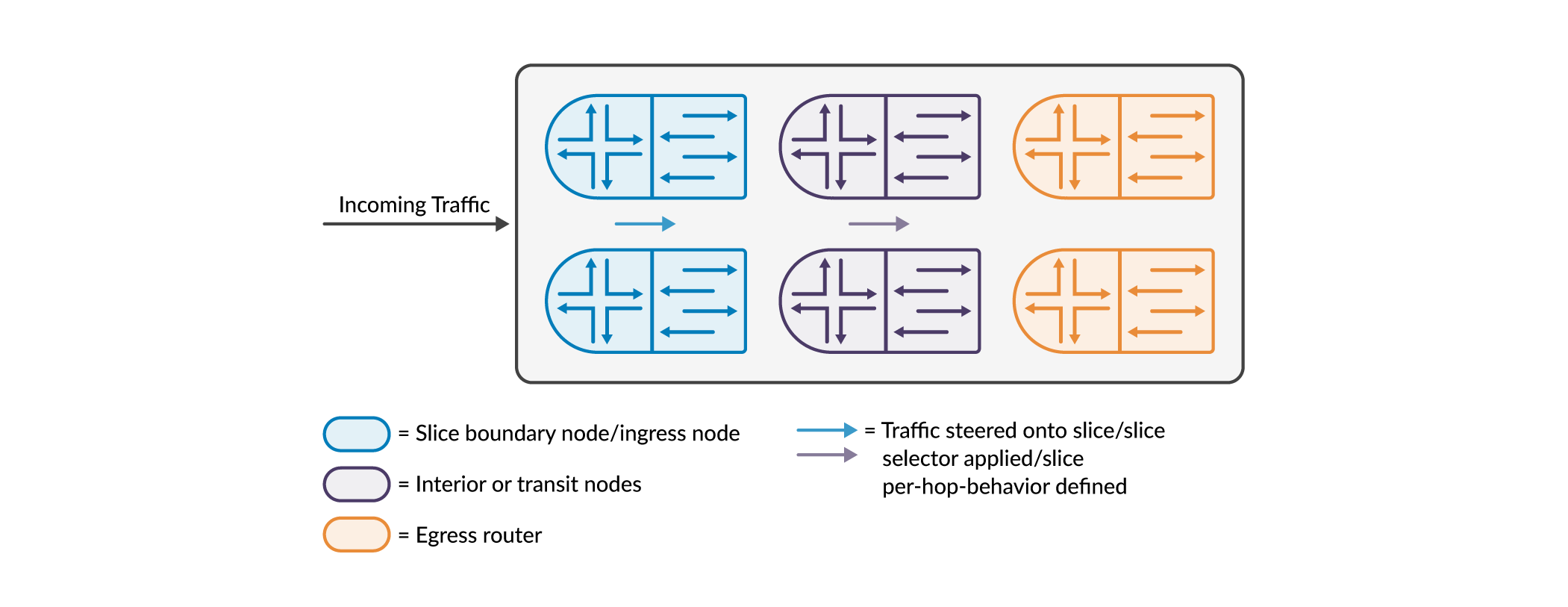
A set of connected physical nodes such as routers and switches (along with their links) that participate in network slicing is called a slice domain. The slice domain has ingress nodes, transit nodes, and egress nodes. Ingress and egress nodes are located at the borders of the slice domain. The ingress nodes receive traffic into the domain and may classify them before forwarding them to the transit nodes. The egress nodes forward traffic out of the slice domain, and before doing so, may classify the packets.

Slice Selector
By definition, a slice selector is information in the packet header. The information is used by the boundary nodes and/or transit nodes of a slice domain to classify and/or process packets. There are various options to encapsulate/identify/designate a slice selector in the packet. As an example, a Service Label in the packet header can be used as a slice selector. If defined, this label is allotted a position in the packet header and is checked at this position by firewall filters to determine/designate slices. Similarly, there are several other options as depicted in the following figure.

Workflow for Creating Slices
Slices as entities are created by specifying them under network slicing hierarchy under services. Then these slices are used to steer packets and to manage traffic destined to slices.
Hierarchical class of service for slices
You define a traffic control profile for a slice under a physical or aggregated Ethernet interface. Note that you can define traffic control profiles for multiple slices under a physical or aggregated Ethernet interface. See slice (CoS Interfaces).
See Hierarchical Class of Service (CoS) Queuing for Slice Per-hop-behavior to understand how slices (as part of a hierarchy) are used to control traffic.
Packet steering
Packet steering is the process of marking/matching packets to/from slices. Packets can be steered using firewall filters (firewall steering) and/or routing policy (route steering).
Firewall steering
A firewall filter can be used at the ingress node to mark matched packets as belonging to slices using the “slice” action. See slice (firewall filter action).
A firewall filter can also be used at the transit node to match slice packets using the “slice” match condition. See slice (firewall filter match condition). The packet can then be marked to another slice if required by the firewall filter or a policer applied to this packet etc.
Packets that are not marked/matched to to/from slices are processed as non-slice traffic.
Route steering
An export policy can be used at the ingress and/or transit node to mark matched routes as belonging to slices. See slice (export routing policy action).
The export policy can also attach a firewall filter to the route. The firewall filter is used to typically apply a policer to the packets matching the route on the ingress side. This firewall filter is not attached to any interface. Rather, it is part of the forwarding information of the route. See filter (export routing policy action).
The slice and/or firewall filter will be part of the route’s next-hop forwarding information. See show route extensive expanded-nh to view slices and/or firewall filters attached to routes.
Packets that do not match routes with slice information, are classified as non-slice traffic. Packets that match routes with no slice information, are also classified as non-slice traffic.
To summarize, the following are the configurations that are to be enabled before creating slices, can be used to create slices, or manage packets belonging to slices.
Specify the slices under network slicing hierarchy under services- – Refer to network-slicing.
Enable enhanced-ip mode – Refer network-services.
Perform class of service configuration to enable a slice under an interface and also apply an output traffic control profile for the slice – See slice (CoS Interfaces). See Hierarchical Class of Service (CoS) Queuing for Slice Per-hop-behavior to understand how slices (as part of a hierarchy) are used to control traffic.
Configure firewall filters to steer routes to slices and/or match routes from slices – See slice (firewall filter match condition) and slice (firewall filter action).
Use routing policy to steer routes to slices and/or attach firewall – See slice (export routing policy action) and filter (export routing policy action).
View slices and/or firewall filters attached to routes. See show route extensive <route> expanded-nh.
View slices attached to the forwarding table. See show class-of-service forwarding-table slice.
Show mapping of traffic control profiles to slices. See show class-of-service forwarding-table slice mapping.
View traffic control profile(s) attached to a slice under an interface. See show class-of-service slice <slice_name> interface <interface_name>.
View statistics for a slice. See show cos halp flow queue-stats.
Hierarchical Class of Service (CoS) Queuing for Slice Per-hop-behavior
In hierarchical CoS, packets are classified at various levels. It could be at the port level, followed by the logical unit level, and then at the queue level. This means that packets are passing through a hierarchy. At every stage of the hierarchy, packets are being classified, shaped, scheduled etc.
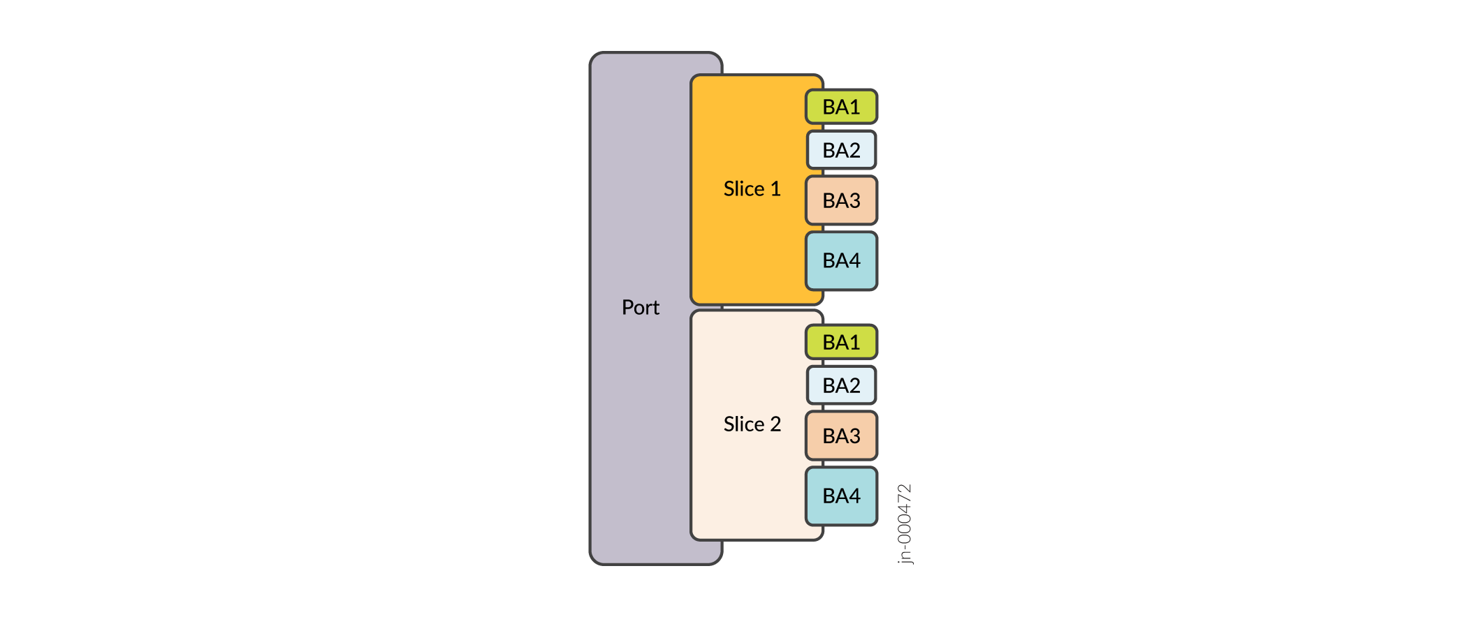
In the context of network slicing, a slice also becomes part of the hierarchy. Shapers, schedulers, and traffic control profiles can be applied to the slice. Just as queues are made available to logical units, queues are made available to slices as well.
As the following figure shows, the queues (labeled BA1, BA2, BA3, BA4) are made available to the slice. The queues map to forwarding classes (FCs). Based on behavioral aggregate classifiers, packets are classified into FCs, and subsequently into a corresponding queue (BA1 or BA2 or BA3 etc.).

As Workflow for Creating Slices describes, you configure network slicing using a combination of firewall filters and Class of Service (CoS) configuration. See slice (CoS Interfaces) to read on how to enable slice(s) under any interface using CoS configuration.