Example: Troubleshoot a VXLAN Overlay Network with Overlay Ping and Overlay Traceroute for MX Series Routers
In a Virtual Extensible LAN (VXLAN) overlay
network, the existing ping and traceroute commands
can verify the basic connectivity between two Juniper Networks devices
that function as virtual tunnel endpoints (VTEPs) in the underlying
physical network. However, in between the two VTEPs, there could be
multiple routes through intermediary devices, and the ping and traceroute
packets might successfully reach their destinations, while a connectivity
issue exists in another route along which the data packets are typically
forwarded to reach their destination.
With the introduction of the overlay parameter and
other options in Junos OS Release 16.2 for MX Series routers, you
can use the ping and traceroute commands to
troubleshoot a VXLAN.
For ping and traceroute mechanisms to work in a VXLAN, the ping and traceroute packets, also referred to as Operations, Administration, and Management (OAM) packets, must be encapsulated with the same VXLAN headers (outer headers) as the data packets forwarded over the VXLAN segment with possible connectivity issues. If any connectivity issues arise, the overlay OAM packet would experience the same issues as the data packet.
This example shows how to use overlay ping and traceroute on a VTEP to verify the following in a VXLAN:
Scenario 1—Verify that a particular VXLAN is configured on another VTEP.
Scenario 2—Verify that the MAC address of a particular endpoint is associated with a VXLAN on the remote VTEP.
Scenario 3—Verify that no issues exist in a particular data flow between sending and receiving endpoints.
When issuing the ping overlay and traceroute
overlay commands, the source VTEP on which you issue the command
and the destination VTEP that receives the ping packet must be Juniper
Networks devices that support overlay ping and traceroute.
Requirements
This example uses the following hardware and software components:
Three physical servers on which applications directly run.
Two MX Series routers running Junos OS Release 16.2 or later software. These routers function as VTEPs.
Two Layer 3 routers, which can be Juniper Networks routers or routers provided by another vendor.
Before issuing the ping overlay and traceroute overlay commands, gather the information
needed for each parameter— for example, IP addresses or MAC
addresses— used for a particular scenario. See Table 1 to determine which parameters
are used for each scenario.
Overview and Topology
The VXLAN topology shown in Figure 1 includes physical servers A, B, and C on which applications directly run. The applications on physical servers A and B need to communicate with the applications on physical server C. These servers are on the same subnet, so the communication between the applications occurs at the Layer 2 level, and VXLAN encapsulation or tunnels are used to transport their data packets over a Layer 3 network.
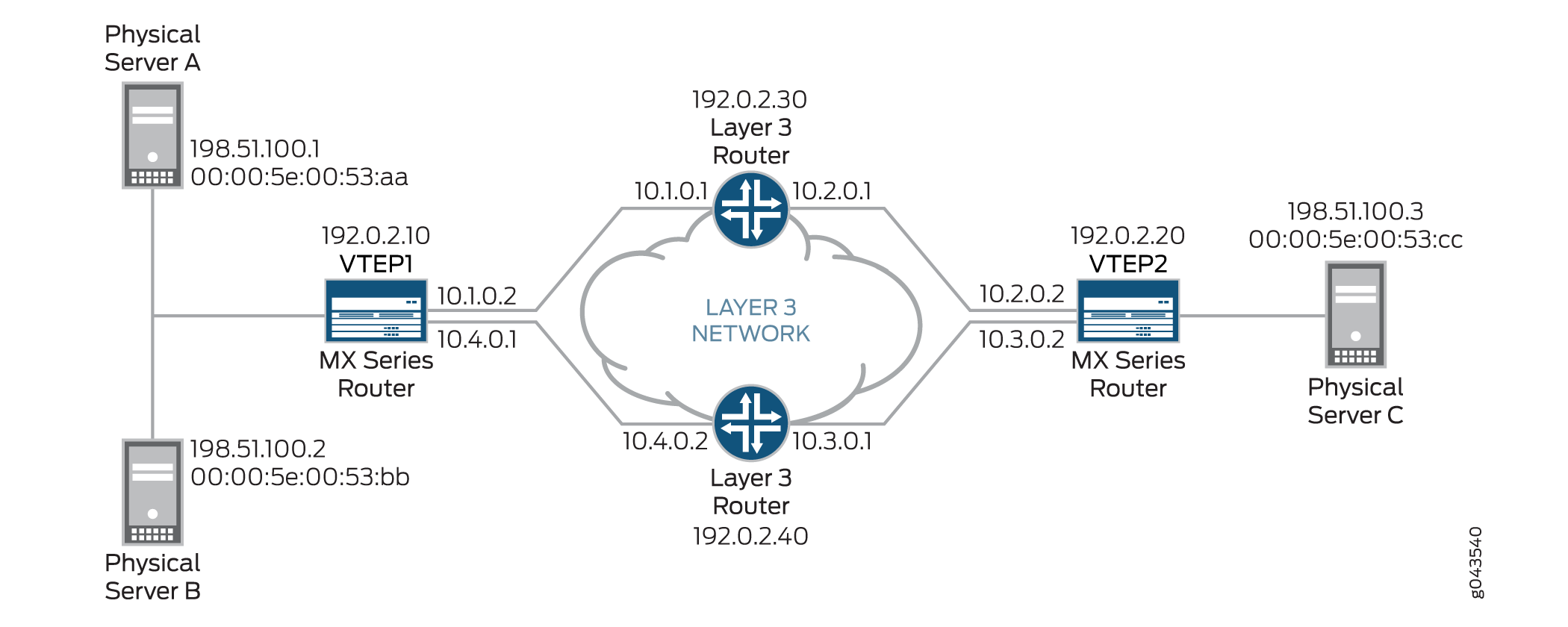
In this topology, there are two MX Series routers that function as VTEPs. VTEP1 initiates and terminates VXLAN tunnels for physical servers A and B, and VTEP2 does the same for physical server C. VTEP1 and VTEP2 are in VXLAN 100.
A data packet sent from physical server A is typically routed to the Layer 3 router with the IP address of 192.0.2.30 to reach physical server C.
In this VXLAN topology, a communication issue arises between
physical servers A and C. To troubleshoot the issue with this data
flow, you can initiate the ping overlay and traceroute
overlay commands on VTEP1 (the source VTEP or tunnel-src) and specify that VTEP2 is the destination VTEP or tunnel-dst.
The ping overlay and traceroute overlay commands include several parameters. Table 1 explains the purpose and provides
a value for each of the parameters used in the three scenarios.
Table 1 does not include
all available ping overlay and traceroute overlay parameters. This example uses the default values of these omitted
parameters.
|
Description |
Scenario to Which Parameter Applies |
Value |
|---|---|---|---|
|
Identifies type of tunnel that you are troubleshooting. |
All |
vxlan |
|
VXLAN network identifier (VNI) of VXLAN used in this example. |
All |
100 |
|
IP address of VTEP1, on which you initiate overlay ping or traceroute. |
All |
192.0.2.10 |
|
IP address of VTEP2, which receives the overlay ping or traceroute packets. |
All |
192.0.2.20 |
|
MAC address of physical server C, which is the destination endpoint. |
Scenarios 2 and 3 |
00:00:5E:00:53:cc |
|
Number of overlay ping requests that VTEP1 sends. Note:
The count parameter does not apply to overlay traceroute. |
All |
5 |
|
MAC address of physical server A, which is the source endpoint. |
Scenario 3 |
00:00:5E:00:53:aa |
|
MAC address of physical server C, which is the destination endpoint. Note:
When specifying this parameter for scenario 3, the MAC
address must be the same MAC address as specified for the |
Scenario 3 |
00:00:5E:00:53:cc |
|
IP address of physical server A. |
Scenario 3 |
198.51.100.1 |
|
IP address of physical server C. |
Scenario 3 |
198.51.100.3 |
|
A value for the protocol used in the data flow. |
Scenario 3 |
17 |
|
A value for the outer TCP/UDP source port. |
Scenario 3 |
4456 |
|
A value for the outer UDP destination port. |
Scenario 3 |
4540 |
Table 1 includes several hash parameters, which are used for scenario 3. For each of these parameters, you must specify a value associated with the data flow that you are troubleshooting. Based on the values that you specify, the system calculates a VXLAN UDP header source port hash, which is included in the VXLAN UDP header of the overlay ping and traceroute packets. Including the calculated hash in the VXLAN UDP header enables the overlay ping and traceroute packets to emulate data packets in the flow that you are troubleshooting.
When using the hash parameters, we recommend that you specify a value for each parameter. This practice ensures that the overlay ping and traceroute processes are successful and that the output for each command is accurate. If you do not specify a value for one or more of the hash parameters, the system sends an OAM request that might include incorrect hash values and generates a warning message.
Configuration
Verification
This section includes the following verification tasks:
- Scenario-1: Verifying That VXLAN 100 Is Configured on VTEP2
- Scenario 2: Verifying That the MAC Address of the Destination Endpoint Is on VTEP2
- Scenario 3: Verifying a Data Flow
Scenario-1: Verifying That VXLAN 100 Is Configured on VTEP2
Purpose
Verify that a VXLAN with the VNI of 100 is configured on VTEP2. You can use either overlay ping or traceroute to perform this verification.
Action
Overlay Ping
On VTEP1, initiate an overlay ping:
user@switch> ping overlay tunnel-type vxlan vni 100 tunnel-src 192.0.2.10 tunnel-dst 192.0.2.20 count 5
ping-overlay protocol vxlan

					       vni 100
					       tunnel src ip 192.0.2.10
            tunnel dst ip 192.0.2.20
            mac address 00:00:00:00:00:00
            count 5
            ttl 255

        WARNING: following hash-parameters are missing -
                hash computation may not succeed

                end-host smac
                end-host dmac
                end-host src ip
                end-host dst ip
                end-host protocol
                end-host l4-src-port
                end-host l4-dst-port
Request for seq 1, to 192.0.2.20, at 09-24 22:03:16 PDT.033 msecs

Response for seq 1, from 192.0.2.20, at 09-24 22:03:16 PDT.036 msecs, rtt 10 msecs

  Overlay-segment  not present at RVTEP 192.0.2.20


Request for seq 2, to 192.0.2.20, at 09-24 22:03:16 PDT.044 msecs

Response for seq 2, from 192.0.2.20, at 09-24 22:03:16 PDT.046 msecs, rtt 10 msecs

  Overlay-segment  not present at RVTEP 192.0.2.20


Request for seq 3, to 192.0.2.20, at 09-24 22:03:16 PDT.054 msecs

Response for seq 3, from 192.0.2.20, at 09-24 22:03:16 PDT.057 msecs, rtt 10 msecs

  Overlay-segment  not present at RVTEP 192.0.2.20


Request for seq 4, to 192.0.2.20, at 09-24 22:03:16 PDT.065 msecs

Response for seq 4, from 192.0.2.20, at 09-24 22:03:16 PDT.069 msecs, rtt 10 msecs

  Overlay-segment  not present at RVTEP 192.0.2.20

Request for seq 5, to 192.0.2.20, at 09-24 22:03:16 PDT.076 msecs

Response for seq 5, from 192.0.2.20, at 09-24 22:03:16 PDT.079 msecs, rtt 10 msecs

  Overlay-segment  not present at RVTEP 192.0.2.20
Overlay Traceroute
On VTEP1, initiate an overlay traceroute:
user@switch> traceroute overlay tunnel-type vxlan vni 100 tunnel-src 192.0.2.10 tunnel-dst 192.0.2.20
traceroute-overlay protocol vxlan

 			 			   vni 100
       			 tunnel src ip 192.0.2.10
       			 tunnel dst ip 192.0.2.20
       			 mac address 00:00:00:00:00:00
       			 ttl 255

        WARNING: following hash-parameters are missing -
                hash computation may not succeed

                end-host smac
                end-host dmac
                end-host src ip
                end-host dst ip
                end-host protocol
                end-host l4-src-port
                end-host l4-dst-port
ttl  Address    Sender Timestamp               Receiver Timestamp             Response Time
  1   10.1.0.2   09-25 00:51:10 PDT.599 msecs            *                     10 msecs
  2   192.0.2.20   09-25 00:51:10 PDT.621 msecs   09-25 00:51:10 PDT.635 msecs   21 msecs

  Overlay-segment not present at RVTEP 192.0.2.20
Meaning
The sample overlay ping output indicates the following:
VTEP1 sent five ping requests to VTEP2, and VTEP2 responded to each request.
VTEP2 indicated that the VNI of 100 is not configured (
Overlay-segment not present at RVTEP 192.0.2.20) and included this information in its response to VTEP1.
The sample overlay traceroute output indicates the following:
Upon receiving an overlay traceroute packet with a time-to-live (TTL) value of 1 hop, the Layer 3 router responds to VTEP1.
Upon receiving an overlay traceroute packet with a TTL value of 2 hops, VTEP2 responds to VTEP1.
VTEP2 indicated that the VNI of 100 is not configured (Overlay-segment not present at RVTEP 192.0.2.20) and included this information in its response to VTEP1.
The asterisk (*) in the Receiver Timestamp column of the overlay traceroute output indicates that the Layer 3 router that received the overlay traceroute packet is not a Juniper Networks device or is a Juniper Networks device that does not support overlay traceroute.
Given that the output of both overlay ping and traceroute indicates that VXLAN 100 is not present, check for this configuration on VTEP2. If you must configure a VNI of 100 on VTEP2, use the vni configuration statement at the [edit vlans vlan-id vxlan] hierarchy level, and reissue the ping overlay or traceroute overlay command to verify that VXLAN 100 is now recognized.
Scenario 2: Verifying That the MAC Address of the Destination Endpoint Is on VTEP2
Purpose
Verify that the MAC address (00:00:5E:00:53:cc) of physical server C, which is the destination endpoint, is in the forwarding table of VTEP2. You can use either overlay ping or traceroute to perform this verification.
Action
Overlay Ping
On VTEP1, initiate an overlay ping:
user@switch> ping overlay tunnel-type vxlan vni 100 tunnel-src 192.0.2.10 tunnel-dst 192.0.2.20 mac 00:00:5E:00:53:cc count 5
ping-overlay protocol vxlan

   					   vni 100
       		  tunnel src ip 192.0.2.10
        			tunnel dst ip 192.0.2.20
        			mac address 00:00:5E:00:53:cc
        			count 5
        			ttl 255

        	WARNING: following hash-parameters are missing -
               		 hash computation may not succeed

                end-host smac
                end-host dmac
                end-host src ip
                end-host dst ip
                end-host protocol
                end-host l4-src-port
                end-host l4-dst-port
Request for seq 1, to 192.0.2.20, at 09-24 23:53:54 PDT.089 msecs

Response for seq 1, from 192.0.2.20, at 09-24 23:53:54 PDT.089 msecs, rtt 6 msecs

  Overlay-segment present at RVTEP 192.0.2.20

      End-System Not Present


Request for seq 2, to 192.0.2.20, at 09-24 23:53:54 PDT.096 msecs

Response for seq 2, from 192.0.2.20, at 09-24 23:53:54 PDT.100 msecs, rtt 10 msecs

  Overlay-segment present at RVTEP 192.0.2.20

      End-System Not Present


Request for seq 3, to 192.0.2.20, at 09-24 23:53:54 PDT.107 msecs

Response for seq 3, from 192.0.2.20, at 09-24 23:53:54 PDT.111 msecs, rtt 10 msecs

  Overlay-segment present at RVTEP 192.0.2.20

      End-System Not Present

Request for seq 4, to 192.0.2.20, at 09-24 23:53:54 PDT.118 msecs

Response for seq 4, from 192.0.2.20, at 09-24 23:53:54 PDT.122 msecs, rtt 11 msecs

  Overlay-segment present at RVTEP 192.0.2.20

      End-System Not Present


Request for seq 5, to 192.0.2.20, at 09-24 23:53:54 PDT.129 msecs

Response for seq 5, from 192.0.2.20, at 09-24 23:53:54 PDT.133 msecs, rtt 10 msecs

  Overlay-segment present at RVTEP 192.0.2.20

      End-System Not Present
Overlay Traceroute
On VTEP1, initiate an overlay traceroute:
user@switch> traceroute overlay tunnel-type vxlan vni 100 tunnel-src 192.0.2.10 tunnel-dst 192.0.2.20 mac 00:00:5E:00:53:cc
traceroute-overlay protocol vxlan


						    vni 100
     			  tunnel src ip 192.0.2.10
      				tunnel dst ip 192.0.2.20
       			mac address 00:00:5E:00:53:cc
       			ttl 255

        WARNING: following hash-parameters are missing -
                hash computation may not succeed

                end-host smac
                end-host dmac
                end-host src ip
                end-host dst ip
                end-host protocol
                end-host l4-src-port
                end-host l4-dst-port

ttl  Address    Sender Timestamp               Receiver Timestamp             Response Time
  1   10.1.0.1   09-25 00:56:17 PDT.663 msecs            *                     10 msecs
  2   192.0.2.20   09-25 00:56:17 PDT.684 msecs   09-25 00:56:17 PDT.689 msecs   11 msecs

  Overlay-segment present at RVTEP 192.0.2.20

      End-System not Present
Meaning
The sample overlay ping output indicates the following:
VTEP1 sent five ping requests to VTEP2, and VTEP2 responded to each request.
VTEP2 verified that the VNI of 100 is configured (
Overlay-segment present at RVTEP 192.0.2.20) but that the MAC address of physical server C is not in the forwarding table (End-System Not Present). VTEP2 included this information in its response to VTEP1.
The sample overlay traceroute output indicates the following:
Upon receiving an overlay traceroute packet with a TTL value of 1 hop, the Layer 3 router responds to VTEP1.
Upon receiving an overlay traceroute packet with a TTL value of 2 hops, VTEP2 responds to VTEP1.
VTEP2 verified that the VNI of 100 is configured (
Overlay-segment present at RVTEP 192.0.2.20) and that the MAC address of physical server C is in the forwarding table (End-System Present). VTEP2 included this information in its response to VTEP1.
The asterisk (*) in the Receiver Timestamp column of the overlay traceroute output indicates that the Layer 3 router that received the overlay traceroute packet is not a Juniper Networks device or is a Juniper Networks device that does not support overlay traceroute.
Given that the output of both overlay ping and traceroute indicates that the MAC address of physical server C is not known by VTEP2, you must further investigate to determine why this MAC address is not in the forwarding table of VTEP2.
Scenario 3: Verifying a Data Flow
Purpose
Verify that there are no issues that might impede the flow of data from physical server A to physical server C. The networking devices that support this flow include VTEP1, the Layer 3 router with the IP address of 192.0.2.30, and VTEP2 (see Figure 1).
Initially, use overlay ping, and if the overlay ping results indicate an issue, use overlay traceroute to determine which device in the path has an issue.
With both overlay ping and traceroute, use the hash parameters to specify information about the devices in this data flow so that the system can calculate a VXLAN UDP header source port hash, which is included in the VXLAN UDP header of the overlay ping and traceroute packets. With the calculated hash included in the VXLAN UDP header, the overlay ping and traceroute packets can emulate data packets in this flow, which should produce more accurate ping and traceroute results.
Action
Overlay Ping
On VTEP1, initiate an overlay ping:
user@switch> ping overlay tunnel-type vxlan vni 100 tunnel-src 192.0.2.10 tunnel-dst 192.0.2.20 mac 00:00:5E:00:53:cc count 5 hash-source-mac 00:00:5E:00:53:aa hash-destination-mac 00:00:5E:00:53:cc hash-source-address 198.51.100.1 hash-destination-address 198.51.100.3 hash-protocol 17 hash-source-port 4456 hash-destination-port 4540
ping-overlay protocol vxlan

        vni 100
        tunnel src ip 192.0.2.10
        tunnel dst ip 192.0.2.20
        mac address 00:00:5E:00:53:cc
        count 5
        ttl 255

        hash-parameters:
                input-ifd-idx 653
                end-host smac 00:00:5E:00:53:aa
                end-host dmac 00:00:5E:00:53:cc
                end-host src ip 198.51.100.1
                end-host dst ip 198.51.100.3
                end-host protocol 17
                end-host l4-src-port 4456
                end-host l4-dst-port 4540end-host vlan 150
Request for seq 1, to 192.0.2.20, at 09-24 19:15:33 PDT.352 msecs
Request for seq 2, to 192.0.2.20, at 09-24 19:15:33 PDT.363 msecs
Request for seq 3, to 192.0.2.20, at 09-24 19:15:33 PDT.374 msecs
Request for seq 4, to 192.0.2.20, at 09-24 19:15:33 PDT.385 msecs
Request for seq 5, to 192.0.2.20, at 09-24 19:15:33 PDT.396 msecs
Overlay Traceroute
If needed, on VTEP1, initiate an overlay traceroute:
user@switch> traceroute overlay tunnel-type vxlan vni 100 tunnel-src 192.0.2.10 tunnel-dst 192.0.2.20 mac 00:00:5E:00:53:cc hash-source-mac 00:00:5E:00:53:aa hash-destination-mac 00:00:5E:00:53:cc hash-source-address 198.51.100.1 hash-destination-address 198.51.100.3 hash-protocol 17 hash-source-port 4456 hash-destination-port 4540
traceroute-overlay protocol vxlan

        vni 100
        tunnel src ip 192.0.2.10
        tunnel dst ip 192.0.2.20
        mac address 00:00:5E:00:53:cc
        ttl 255

        hash-parameters:
                input-ifd-idx 653
                end-host smac 00:00:5E:00:53:aa
                end-host dmac 00:00:5E:00:53:cc
                end-host src ip 198.51.100.1
                end-host dst ip 198.51.100.3
                end-host protocol 17
                end-host l4-src-port 4456
                end-host l4-dst-port 4540

ttl  Address    Sender Timestamp               Receiver Timestamp             Response Time
  1   10.1.0.1   09-25 00:56:17 PDT.663 msecs            *                     10 msecs
Meaning
The sample overlay ping output indicates that VTEP1 sent five ping requests to VTEP2, but VTEP2 did not respond to any of the requests. The lack of response from VTEP2 indicates that a connectivity issue exists along the path between VTEP1 and the Layer 3 router or the path between the Layer 3 router and VTEP2.
To further troubleshoot in which path the issue lies, overlay traceroute is used.The sample overlay traceroute output indicates the following:
Upon receiving an overlay traceroute packet with a TTL value of 1 hop, the Layer 3 router responds to VTEP1, which indicates that the path between VTEP1 and the Layer 3 router is up.
VTEP2 does not respond to the overlay traceroute packet, which indicates that the path between the Layer 3 router and VTEP2 might be down.
The asterisk (*) in the Receiver Timestamp column of the overlay traceroute output indicates that the Layer 3 router that received the overlay traceroute packet is not a Juniper Networks device or is a Juniper Networks device that does not support overlay traceroute.
Given that the overlay traceroute output indicates that there is a connectivity issue between the Layer 3 router and VTEP2, you must further investigate this path segment to determine the source of the issue.