Overview of Flexible Cross-Connect Support on VPWS with EVPN
Ethernet VPN virtual private wire service (EVPN-VPWS) delivers point-to-point Ethernet services between a pair of attachment circuits. An attachment circuit is an access interface participating in an EVPN E-LINE service. EVPN-VPWS also provides multihoming and fast convergence capabilities. With EVPN-VPWS flexible cross-connect (FXC), you can multiplex a large number of attachment circuits across several physical interfaces onto a single VPWS service tunnel.
EVPN-VPWS FXC was introduced as a standard to address label resource issues that can occur on some low end access routers. FXC can bundle a group of attachment circuits under the same EVPN-VPWS instance to share the same MPLS label. You can use FXC to bundle attachment circuits into a single point-to-point Ethernet service group with the normalized VLAN tags used in the data plane. Attachment circuits that share the same label share the same EVPN-VPWS service tunnel.
The MPLS label resource issue isn't applicable on provider edge (PE) devices (also called service edge routers), MX access routers, or vMX access routers that use pseudowire subscriber logical interfaces. (See MPLS Pseudowire Subscriber Logical Interfaces for more on this type of logical interface.)
With FXC, the control plane signaling is based on the exchange of EVPN Ethernet Auto-Discovery (A-D) per EVPN instance (EVI) routes between a pair of PE devices. All the point-to-point Ethernet services under the same EVI are uniquely identified by either a single VLAN tag or double VLAN tags. To ensure the uniqueness, the device must perform VLAN normalization at the ingress. This requirement applies on both PE devices for VLAN unaware and VLAN aware services.
When you use the FXC service on access routers, the forwarding plane uses the MPLS label to find the EVPN-VPWS instance to which a point-to-point Ethernet service belongs. The access router and the service edge router (PE device) use the VLAN(s) carried in the data packet as the de-multiplexer to uniquely identify each local attachment circuit for a point-to-point Ethernet service.
The two types of EVPN-VPWS FXC services are:
-
VLAN unaware service—The default EVPN-VPWS FXC service.
With this service type, the device signals a single Ethernet A-D per EVI route for each bundle of attachment circuits. The device continues to advertise this route until all attachment circuits in the same group go down. In contrast, a traditional EVPN-VPWS service uses an Ethernet A-D per EVI route for each attachment circuit. The device withdraws that route when the corresponding attachment circuit goes down.
-
VLAN aware service—A VLAN-signaled EVPN-VPWS FXC service.
With this service type, the device advertises one Ethernet A-D per EVI route for each attachment circuit in the same bundle. All the Ethernet A-D per EVI routes for those attachment circuits share the same service label. However, in this case, the device advertises and withdraws each Ethernet A-D per EVI route in the same way as the traditional EVPN-VPWS service. In other words, when a specific attachment circuit goes down, the device withdraws its corresponding Ethernet A-D per EVI route.
Benefits of Pseudowire Headend Termination (PWHT) with EVPN-VPWS FXC Service
EVPN-VPWS FXC is an extension to basic EVPN-VPWS that:
-
Bundles different attachment circuits under the same EVI on an access node to share the same EVPN-VPWS service tunnel (also called an EVPN-VPWS pseudowire). In this way, multiple E-LINE services can share the same EVPN-VPWS service tunnel or pseudowire.
-
Supports all true VLAN aware bundle services for the VLAN-signaled FXC.
-
Uses MPLS label resources more efficiently to support lower-end access devices.
FXC on Service Edge Routers
With PWHT that uses EVPN-VPWS FXC services, the PE device acts as a service edge router. The PE device:
-
Performs PWHT through each pseudowire subscriber interface.
-
Allocates a label for each pseudowire subscriber interface (with a VLAN unaware FXC service) or for the EVI (with a VLAN aware FXC service).
-
Interoperates with the access router, which uses a different label allocation scheme (the access router might use a traditional EVPN-VPWS service or an EVPN-VPWS FXC service).
The pseudowire subscriber transport logical interfaces use encapsulation type
ethernet-ccc, and provide a VLAN bundle service.
Similarly, FXC bundles together a group of attachment circuits. We identify each point-to-point Ethernet service in the same group by its unique normalized VLAN(s) in the data plane.
VLAN Unaware FXC on Service Edge Routers
- Access-side Single-homing Support for a VLAN Unaware FXC Service
- Access-side Multihoming Support for VLAN Unaware FXC Service
Access-side Single-homing Support for a VLAN Unaware FXC Service
We support single-homed end devices on access-side router attachment circuits. In this case, all attachment circuits in the same EVI are multiplexed (bundled) into a single EVPN-VPWS service tunnel. This bundle shares a service instance ID and MPLS service label. The access routers advertise only one Ethernet A-D per EVI route for the attachment circuit bundle.
The access router doesn't withdraw an advertised Ethernet A-D per EVI route for an attachment circuit bundle until either of the following happen:
-
All of the attachment circuits in the bundle go down.
-
You deactivate or delete the EVI.
To terminate an attachment circuit bundle at the access router, on the PE device you must configure a separate pseudowire subscriber transport logical interface with the corresponding service instance ID. Do this for each bundle of access interfaces at the access router . The pseudowire subscriber transport logical interface works in VLAN bundle mode.
Access-side Multihoming Support for VLAN Unaware FXC Service
Attachment circuits that share an Ethernet segment identifier (ESI) are bundled together. Attachment circuits in the same group share the same local service instance ID. With FXC multihoming, the access router advertises a separate Ethernet A-D route for each multihomed Ethernet segment. The same PE device acts as the designated forwarder (DF) or non-designated forwarder (NDF) for the attachment circuits in the same Ethernet segment at the same time. However, note that the same PE might also be the DF and NDF independently for different Ethernet segments.
You must use different pseudowire subscriber transport logical interfaces to terminate different multihomed attachment circuit bundles. You can't bundle different multihomed Ethernet segments at the access routers into the same group. This is because the device only has one Ethernet A-D per EVI route for each multihomed Ethernet segment, and each multihomed Ethernet segment must work independently in the forwarding path.
To support interoperability with VLAN unaware multihoming FXC at the access router:
-
Bundle attachment circuits on the same multihomed Ethernet segment to use the same local service instance ID on the access router.
-
Assign a unique local service instance ID to each attachment circuit bundle.
-
At the PE device, use a separate pseudowire subscriber transport logical interface to terminate an access router group of attachment circuits on the same multihomed Ethernet segment.
-
Assign a unique local service instance ID corresponding to each pseudowire subscriber transport logical interface.
Here's an example configuration to create a group that bundles the attachment circuits that
share the same multihomed ESI. You create the group at the [edit <routing-instances
name> protocols evpn] hierarchy level for a VLAN unaware FXC
service at an access router as follows:
set routing-instances EVPN-VPWS-FXC-AE protocols evpn group G1 esi 00:71:81:00:00:00:00:00:00:01;
set routing-instances EVPN-VPWS-FXC-AE protocols evpn group G1 interface ge-0/0/3.1;
set routing-instances EVPN-VPWS-FXC-AE protocols evpn group G1 interface ge-0/0/3.2;
set routing-instances EVPN-VPWS-FXC-AE protocols evpn group G1 service-id local 300;
set routing-instances EVPN-VPWS-FXC-AE protocols evpn group G1 service-id remote 300;
VLAN Aware FXC on Service Edge Routers
On an access router, VLAN aware (VLAN signaled) FXC shares the same MPLS label for a group of attachment circuits in the same EVI. For each attachment circuit in the same group, we:
-
Assign a unique local service instance ID per attachment circuit.
-
Identify the attachment circuit in the forwarding plane with:
-
One unique normalized VLAN ID for single tagged frames.
-
Multiple VLAN IDs for Q-in-Q tagged frames.
-
With a VLAN aware FXC service, we signal each individual point-to-point Ethernet service using a pair of Ethernet A-D routes in the control plane, one for each of its attachment circuits. This is the same as the point-to-point Ethernet service that EVPN-VPWS offers. If you use the FXC service on the access routers running in either single-active or all-active multihomed mode, we recommend you use the VLAN aware service instead of the VLAN unaware service.
The VLAN aware FXC service uses pseudowire subscriber service logical interfaces at the service edge router. This service associates the local service instance ID with the pseudowire subscriber service logical interface (instead of the pseudowire subscriber transport logical interface).
With single-active multihoming, you can configure each pseudowire subscriber service logical interface for an Ethernet segment using an ESI per logical interface.
To support multihoming on the service edge router, you need an ESI configuration for the pseudowire subscriber service logical interface. As a result, the device load-balances the traffic among a set of service edge routers based on the VLAN.
For PE devices interoperating with VLAN aware FXC access routers:
-
This mode uses only one pseudowire subscriber logical interface for each EVI. You can manually configure a pair of local and remote service instance IDs on each of the pseudowire subscriber logical interfaces. Otherwise, the device auto-derives the local service instance ID from the normalized VLAN ID(s), which would produce the same local and remote service instance ID.
-
For single-active multihoming mode, configure a non-reserved ESI for the pseudowire subscriber service logical interface.
-
Each attachment circuit has a separate Ethernet A-D per EVI route advertised with its Ethernet tag ID set to the local service instance ID. You can manually configure the Ethernet tag ID, or the device auto-derives it based on the normalized VLAN ID(s).
Load-Balancing FXC VLAN Aware Service Traffic on PE Devices
To load-balance FXC VLAN aware service traffic on PE devices, you must configure the single-active multihomed Ethernet Segment ID (ESI) under the PS interface with PWHT as shown in the following sample configuration:
Ps0 {
    anchor-point {
        lt-0/2/10;
    }
    flexible-vlan-tagging;
    unit 0 {
        encapsulation ethernet-ccc;
    }
    unit 1 {
        esi {
            00:02:03::01;
            single-active;
        }
        encapsulation vlan-vpls;
        vlan-id 200;
        family vpls;
    }
    unit 2 {
        esi {
            00:03:03::02;
            single-active;
        }
        encapsulation vlan-vpls;
        vlan-id 201;
        family vpls;
    }
}
VLAN Tagging
Pseudowire subscriber logical interfaces support untagged, single-tagged and double-tagged frames. For interoperability with EVPN FXC, the pseudowire subscriber logical interface must support demultiplexing on a single VLAN ID or double VLAN tags (Q-in-Q).
Signaling EVPN FXC Optional Bits
The M-bit and V-bit are optional bits in the EVPN FXC Layer 2 extended community. Devices signal only the M-bit in the EVPN Layer 2 extended community to indicate VLAN unaware or VLAN aware (VLAN signaled) FXC.
Access Side Multihoming
The CE devices can be multihomed to the access routers running in either single-active or all-active mode. The service side routers can be single-homed, or multihomed in single-active mode only.
The next sections describe use cases where the access side routers can operate in single-active or all-active multihoming mode, while the service side routers act in single-active multihoming mode.
We support ACX Series routers only as access side routers for FXC, including ACX5448, ACX710, and ACX7xxxx routers. MX Series routers can be access side or service side routers for FXC.
We support access side ACX Series and MX Series routers only in the following configurations:
-
As access side routers single-homed to a service side PE router
-
As access side routers multihomed to a service side PE router where the service side PE router is in single-homing or single-active multihoming mode
- Access Side Single-active with Service Side Single-active
- Access Side All-active with Service Side Single-active
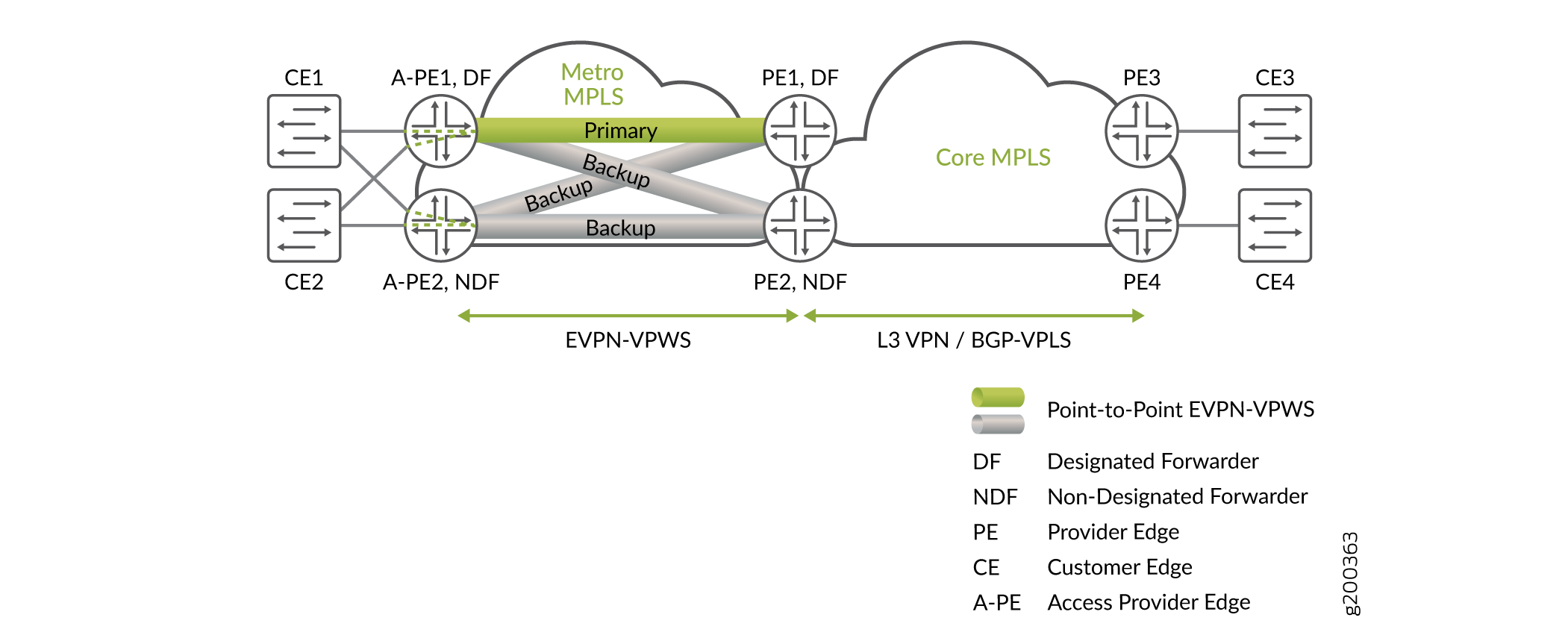
Access Side Single-active with Service Side Single-active
Figure 1 shows a typical square topology with:
-
Two service edge routers, PE1 and PE2.
-
Two access side PE routers, A-PE1 and A-PE2.
Note:We call the access routers A-PE devices in all of the figures in this document to distinguish them from the service edge routers.
A-PE1 and A-PE2 work in single-active mode. One of the service edge routers is elected as DF. One of the access routers is elected as DF. The DF access router and the DF service edge router have only one active or primary pseudowire between them. If one of the DF PE devices has an access link down or suffers node failure, the NDF PE router becomes the DF. As a result, if the existing primary pseudowire goes down, a new primary pseudowire is established among the DF PE devices. This happens per pseudowire subscriber service logical interface (not per PE device).
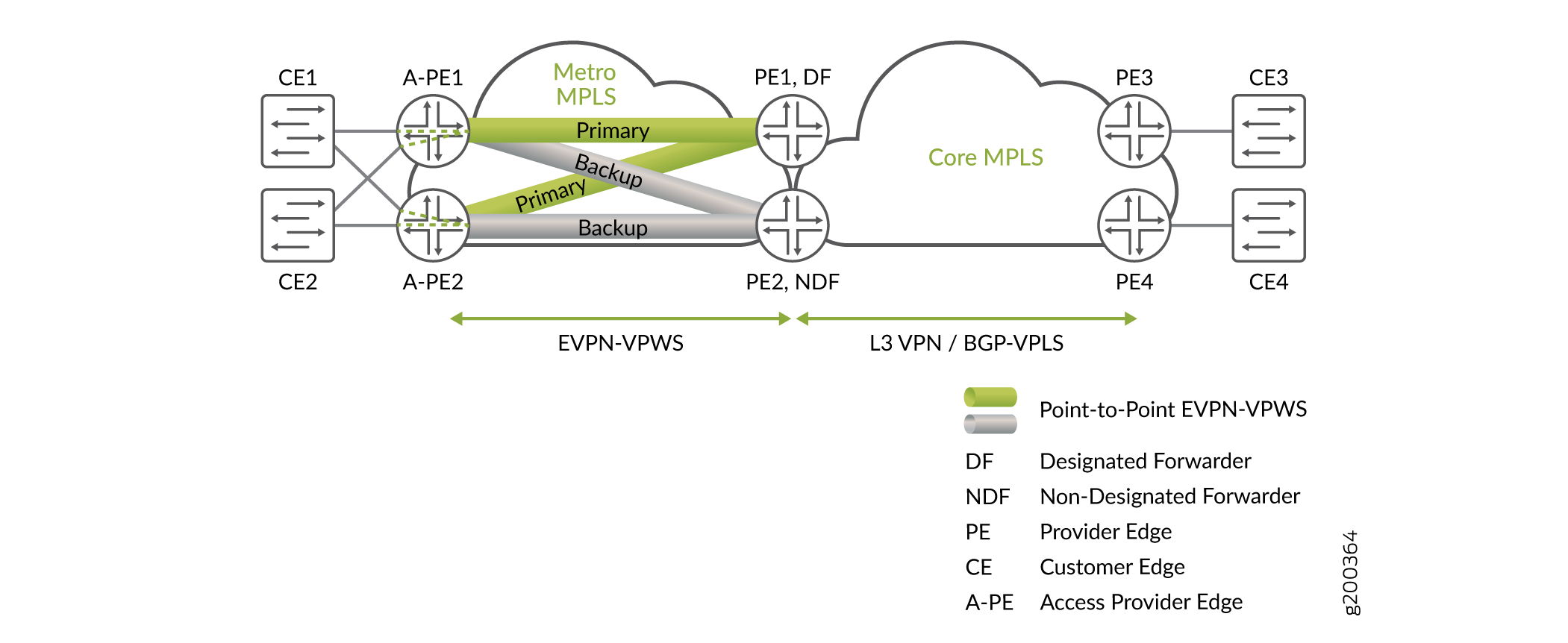
Access Side All-active with Service Side Single-active
Figure 2 shows a square topology with:
-
Two service edger routers, PE1 and PE2.
-
Two A-PE routers, A-PE1 and A-PE2.
A-PE1 and A-PE2 are multihoming peer PE devices in all-active mode for CE devices CE-1 and CE2 on their right side. Both PE devices A-PE1 and A-PE2 can forward the traffic for EVPN-VPWS in this mode.
PE1 and P2 are multihoming peer PE devices in single-active mode for the service. Only one of the PE devices PE1 and PE2 can forward traffic for EVPN-VPWS in this mode. In this figure, PE1 is the DF, so only PE1 forwards the traffic. As a result, this setup establishes two primary pseudowires, one from PE1 to A-PE1 and one from PE1 to A-PE2. To reach CE1 or CE2, PE1 sends the traffic by way of either A-PE1 or A-PE2. PE1 balances the traffic load between those two A-PE devices.