Example: Configuring VPWS with EVPN Signaling Mechanisms
This example shows how to implement Virtual Private Wire Service (VPWS) with Ethernet Virtual Private Network (EVPN) signaling. The use of EVPN signaling provides single-active or all-active multihoming capabilities for BGP-signaled VPNs.
Requirements
This example uses the following hardware and software components:
-
Four MX Series routers acting as provider edge (PE) devices, running Junos OS Release 17.1 or later
-
Two customer edge (CE) devices (MX Series routers are used in this example)
Overview and Topology
VPWS employs Layer 2 VPN services over MPLS to build a topology of point-to-point connections that connect end customer sites. EVPN enables you to connect dispersed customer sites using a Layer 2 virtual bridge. These two elements can be combined to provide an EVPN-signaled VPWS.
The vpws-service-id statement identifies the endpoints
of the EVPN-VPWS based on local and remote service
identifiers configured on the PE routers in the network. These endpoints
are autodiscovered using BGP-based EVPN signaling to exchange the
service identifier labels.
Topology
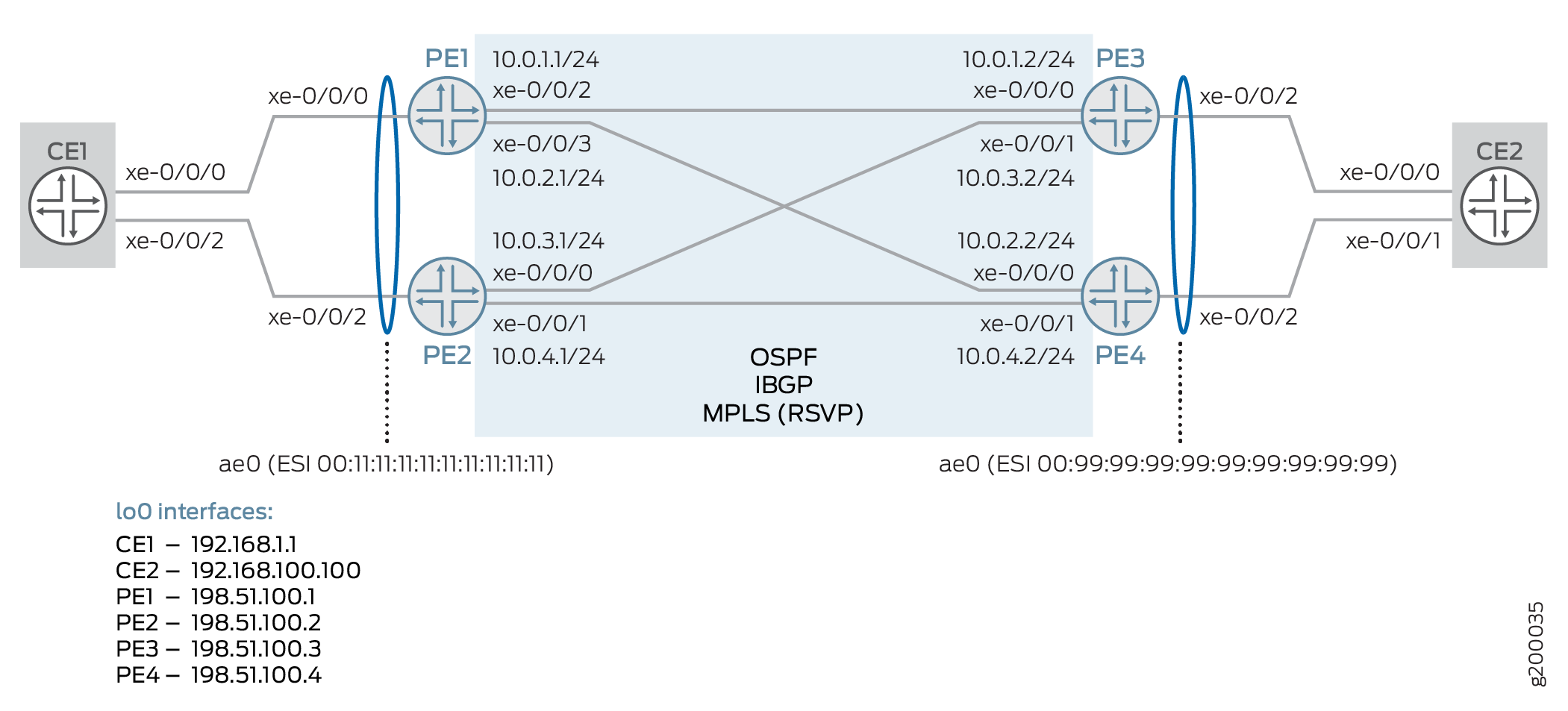
This example uses the topology shown in Figure 1, consisting of four PE routers and two CE routers. Router CE1 is multihomed to Routers PE1 and PE2; Router CE2 is multhomed to Routers PE3 and PE4.
The following configuration elements are used in this scenario:
-
CE devices:
-
Aggregated Ethernet (AE) interface towards related PE devices
-
-
PE devices:
-
AE interface, with EVPN segment identifier (ESI), towards related CE device
-
OSPF and IBGP in the core
-
MPLS LSPs using RSVP in the core
-
Per-packet load balancing
-
Routing instance using instance type
evpn-vpws, and thevpws-service-idstatement to define the local and remote endpoints.
-
Configuration
CLI Quick Configuration
To quickly configure this example, copy the
following commands, paste them into a text file, remove any line breaks,
change any details necessary to match your network configuration,
copy and paste the commands into the CLI at the [edit] hierarchy
level.
CE1
set interfaces xe-0/0/0 gigether-options 802.3ad ae0
set interfaces xe-0/0/2 gigether-options 802.3ad ae0
set chassis aggregated-devices ethernet device-count 1
set interfaces ae0 description "to PE1/2"
set interfaces ae0 flexible-vlan-tagging
set interfaces ae0 encapsulation flexible-ethernet-services
set interfaces ae0 aggregated-ether-options lacp active
set interfaces ae0 unit 100 encapsulation vlan-bridge
set interfaces ae0 unit 100 vlan-id 1000
set interfaces lo0 unit 0 family inet address 192.168.1.1/32
set policy-options policy-statement LB then load-balance per-packet
set routing-options forwarding-table export LB
set bridge-domains bd100 domain-type bridge
set bridge-domains bd100 vlan-id 1000
set bridge-domains bd100 interface ae0.100
CE2
set interfaces xe-0/0/0 gigether-options 802.3ad ae0
set interfaces xe-0/0/1 gigether-options 802.3ad ae0
set chassis aggregated-devices ethernet device-count 1
set interfaces ae0 description "to PE3/4"
set interfaces ae0 flexible-vlan-tagging
set interfaces ae0 encapsulation flexible-ethernet-services
set interfaces ae0 aggregated-ether-options lacp active
set interfaces ae0 unit 100 encapsulation vlan-bridge
set interfaces ae0 unit 100 vlan-id 1000
set interfaces lo0 unit 0 family inet address 192.168.100.100/32
set policy-options policy-statement LB then load-balance per-packet
set routing-options forwarding-table export LB
set bridge-domains bd100 domain-type bridge
set bridge-domains bd100 vlan-id 1000
set bridge-domains bd100 interface ae0.100
PE1
set interfaces xe-0/0/0 description "to CE1"
set interfaces xe-0/0/0 gigether-options 802.3ad ae0
set interfaces xe-0/0/2 unit 0 description "to PE3"
set interfaces xe-0/0/2 unit 0 family inet address 10.0.1.1/24
set interfaces xe-0/0/2 unit 0 family mpls
set interfaces xe-0/0/3 unit 0 description "to PE4"
set interfaces xe-0/0/3 unit 0 family inet address 10.0.2.1/24
set interfaces xe-0/0/3 unit 0 family mpls
set interfaces lo0 unit 0 family inet address 198.51.100.1/32
set chassis aggregated-devices ethernet device-count 1
set interfaces ae0 description "to CE1"
set interfaces ae0 flexible-vlan-tagging
set interfaces ae0 encapsulation flexible-ethernet-services
set interfaces ae0 esi 00:11:11:11:11:11:11:11:11:11
set interfaces ae0 esi all-active
set interfaces ae0 aggregated-ether-options lacp active
set interfaces ae0 aggregated-ether-options lacp system-id 00:00:00:00:00:01
set interfaces ae0 unit 100 encapsulation vlan-ccc
set interfaces ae0 unit 100 vlan-id 1000
set protocols ospf area 0.0.0.0 interface xe-0/0/2.0
set protocols ospf area 0.0.0.0 interface xe-0/0/3.0
set protocols ospf area 0.0.0.0 interface lo0.0
set routing-options autonomous-system 65000
set protocols bgp group IBGP type internal
set protocols bgp group IBGP local-address 198.51.100.1
set protocols bgp group IBGP family evpn signaling
set protocols bgp group IBGP neighbor 198.51.100.2
set protocols bgp group IBGP neighbor 198.51.100.3
set protocols bgp group IBGP neighbor 198.51.100.4
set protocols rsvp interface xe-0/0/2.0
set protocols rsvp interface xe-0/0/3.0
set protocols mpls interface xe-0/0/2.0
set protocols mpls interface xe-0/0/3.0
set protocols mpls no-cspf
set protocols mpls label-switched-path PE1toPE3 to 198.51.100.3
set protocols mpls label-switched-path PE1toPE4 to 198.51.100.4
set policy-options policy-statement LB then load-balance per-packet
set routing-options forwarding-table export LB
set routing-instances EVPN-VPWS instance-type evpn-vpws
set routing-instances EVPN-VPWS interface ae0.100
set routing-instances EVPN-VPWS route-distinguisher 198.51.100.1:11
set routing-instances EVPN-VPWS vrf-target target:100:11
set routing-instances EVPN-VPWS protocols evpn interface ae0.100 vpws-service-id local 1111
set routing-instances EVPN-VPWS protocols evpn interface ae0.100 vpws-service-id remote 9999
PE2
set interfaces xe-0/0/0 unit 0 description "to PE3"
set interfaces xe-0/0/0 unit 0 family inet address 10.0.3.1/24
set interfaces xe-0/0/0 unit 0 family mpls
set interfaces xe-0/0/1 unit 0 description "to PE4"
set interfaces xe-0/0/1 unit 0 family inet address 10.0.4.1/24
set interfaces xe-0/0/1 unit 0 family mpls
set interfaces xe-0/0/2 description "to CE1"
set interfaces xe-0/0/2 gigether-options 802.3ad ae0
set interfaces lo0 unit 0 family inet address 198.51.100.2/32
set chassis aggregated-devices ethernet device-count 1
set interfaces ae0 description "to CE1"
set interfaces ae0 flexible-vlan-tagging
set interfaces ae0 encapsulation flexible-ethernet-services
set interfaces ae0 esi 00:11:11:11:11:11:11:11:11:11
set interfaces ae0 esi all-active
set interfaces ae0 aggregated-ether-options lacp active
set interfaces ae0 aggregated-ether-options lacp system-id 00:00:00:00:00:01
set interfaces ae0 unit 100 encapsulation vlan-ccc
set interfaces ae0 unit 100 vlan-id 1000
set protocols ospf area 0.0.0.0 interface xe-0/0/0.0
set protocols ospf area 0.0.0.0 interface xe-0/0/1.0
set protocols ospf area 0.0.0.0 interface lo0.0
set routing-options autonomous-system 65000
set protocols bgp group IBGP type internal
set protocols bgp group IBGP local-address 198.51.100.2
set protocols bgp group IBGP family evpn signaling
set protocols bgp group IBGP neighbor 198.51.100.1
set protocols bgp group IBGP neighbor 198.51.100.3
set protocols bgp group IBGP neighbor 198.51.100.4
set protocols rsvp interface xe-0/0/0.0
set protocols rsvp interface xe-0/0/1.0
set protocols mpls interface xe-0/0/0.0
set protocols mpls interface xe-0/0/1.0
set protocols mpls no-cspf
set protocols mpls label-switched-path PE2toPE3 to 198.51.100.3
set protocols mpls label-switched-path PE2toPE4 to 198.51.100.4
set policy-options policy-statement LB then load-balance per-packet
set routing-options forwarding-table export LB
set routing-instances EVPN-VPWS instance-type evpn-vpws
set routing-instances EVPN-VPWS interface ae0.100
set routing-instances EVPN-VPWS route-distinguisher 198.51.100.2:11
set routing-instances EVPN-VPWS vrf-target target:100:11
set routing-instances EVPN-VPWS protocols evpn interface ae0.100 vpws-service-id local 1111
set routing-instances EVPN-VPWS protocols evpn interface ae0.100 vpws-service-id remote 9999
PE3
set interfaces xe-0/0/0 unit 0 description "to PE1"
set interfaces xe-0/0/0 unit 0 family inet address 10.0.1.2/24
set interfaces xe-0/0/0 unit 0 family mpls
set interfaces xe-0/0/1 unit 0 description "to PE2"
set interfaces xe-0/0/1 unit 0 family inet address 10.0.3.2/24
set interfaces xe-0/0/1 unit 0 family mpls
set interfaces xe-0/0/2 description "to CE1"
set interfaces xe-0/0/2 gigether-options 802.3ad ae0
set interfaces lo0 unit 0 family inet address 198.51.100.3/32
set chassis aggregated-devices ethernet device-count 1
set interfaces ae0 description "to CE2"
set interfaces ae0 flexible-vlan-tagging
set interfaces ae0 encapsulation flexible-ethernet-services
set interfaces ae0 esi 00:99:99:99:99:99:99:99:99:99
set interfaces ae0 esi all-active
set interfaces ae0 aggregated-ether-options lacp active
set interfaces ae0 aggregated-ether-options lacp system-id 00:00:00:00:00:01
set interfaces ae0 unit 100 encapsulation vlan-ccc
set interfaces ae0 unit 100 vlan-id 1000
set protocols ospf area 0.0.0.0 interface xe-0/0/0.0
set protocols ospf area 0.0.0.0 interface xe-0/0/1.0
set protocols ospf area 0.0.0.0 interface lo0.0
set routing-options autonomous-system 65000
set protocols bgp group IBGP type internal
set protocols bgp group IBGP local-address 198.51.100.3
set protocols bgp group IBGP family evpn signaling
set protocols bgp group IBGP neighbor 198.51.100.1
set protocols bgp group IBGP neighbor 198.51.100.2
set protocols bgp group IBGP neighbor 198.51.100.4
set protocols rsvp interface xe-0/0/0.0
set protocols rsvp interface xe-0/0/1.0
set protocols mpls interface xe-0/0/0.0
set protocols mpls interface xe-0/0/1.0
set protocols mpls no-cspf
set protocols mpls label-switched-path PE3toPE1 to 198.51.100.1
set protocols mpls label-switched-path PE3toPE2 to 198.51.100.2
set policy-options policy-statement LB then load-balance per-packet
set routing-options forwarding-table export LB
set routing-instances EVPN-VPWS instance-type evpn-vpws
set routing-instances EVPN-VPWS interface ae0.100
set routing-instances EVPN-VPWS route-distinguisher 198.51.100.3:11
set routing-instances EVPN-VPWS vrf-target target:100:11
set routing-instances EVPN-VPWS protocols evpn interface ae0.100 vpws-service-id local 9999
set routing-instances EVPN-VPWS protocols evpn interface ae0.100 vpws-service-id remote 1111
PE4
set interfaces xe-0/0/0 unit 0 description "to PE1"
set interfaces xe-0/0/0 unit 0 family inet address 10.0.2.2/24
set interfaces xe-0/0/0 unit 0 family mpls
set interfaces xe-0/0/1 unit 0 description "to PE2"
set interfaces xe-0/0/1 unit 0 family inet address 10.0.4.2/24
set interfaces xe-0/0/1 unit 0 family mpls
set interfaces xe-0/0/2 description "to CE1"
set interfaces xe-0/0/2 gigether-options 802.3ad ae0
set interfaces lo0 unit 0 family inet address 198.51.100.4/32
set chassis aggregated-devices ethernet device-count 1
set interfaces ae0 description "to CE2"
set interfaces ae0 flexible-vlan-tagging
set interfaces ae0 encapsulation flexible-ethernet-services
set interfaces ae0 esi 00:99:99:99:99:99:99:99:99:99
set interfaces ae0 esi all-active
set interfaces ae0 aggregated-ether-options lacp active
set interfaces ae0 aggregated-ether-options lacp system-id 00:00:00:00:00:01
set interfaces ae0 unit 100 encapsulation vlan-ccc
set interfaces ae0 unit 100 vlan-id 1000
set protocols ospf area 0.0.0.0 interface xe-0/0/0.0
set protocols ospf area 0.0.0.0 interface xe-0/0/1.0
set protocols ospf area 0.0.0.0 interface lo0.0
set routing-options autonomous-system 65000
set protocols bgp group IBGP type internal
set protocols bgp group IBGP local-address 198.51.100.4
set protocols bgp group IBGP family evpn signaling
set protocols bgp group IBGP neighbor 198.51.100.1
set protocols bgp group IBGP neighbor 198.51.100.2
set protocols bgp group IBGP neighbor 198.51.100.3
set protocols rsvp interface xe-0/0/0.0
set protocols rsvp interface xe-0/0/1.0
set protocols mpls interface xe-0/0/0.0
set protocols mpls interface xe-0/0/1.0
set protocols mpls no-cspf
set protocols mpls label-switched-path PE4toPE1 to 198.51.100.1
set protocols mpls label-switched-path PE4toPE2 to 198.51.100.2
set policy-options policy-statement LB then load-balance per-packet
set routing-options forwarding-table export LB
set routing-instances EVPN-VPWS instance-type evpn-vpws
set routing-instances EVPN-VPWS interface ae0.100
set routing-instances EVPN-VPWS route-distinguisher 198.51.100.4:11
set routing-instances EVPN-VPWS vrf-target target:100:11
set routing-instances EVPN-VPWS protocols evpn interface ae0.100 vpws-service-id local 9999
set routing-instances EVPN-VPWS protocols evpn interface ae0.100 vpws-service-id remote 1111
Procedure
Step-by-Step Procedure
The following example requires that you navigate various levels in the configuration hierarchy. For information about navigating the CLI, see Using the CLI Editor in Configuration Mode in the CLI User Guide.
Only Router PE1 is shown here. Repeat this procedure for all other PE devices, using the appropriate interface names, addresses, and other parameters for each device.
The step-by-step procedure for CE devices is not shown.
To configure Router PE1:
-
Configure the CE-facing interface to be part of the ae0 bundle.
The second interface for the AE bundle will be configured on the other local PE device.
[edit interfaces]
user@PE1# set xe-0/0/0 description "to CE1"
user@PE1# set xe-0/0/0 gigether-options 802.3ad ae0
-
Configure the core-facing interfaces toward Routers PE3 and PE4.
Be sure to include the MPLS protocol family.
[edit interfaces]
user@PE1# set xe-0/0/2 unit 0 description "to PE3"
user@PE1# set xe-0/0/2 unit 0 family inet address 10.0.1.1/24
user@PE1# set xe-0/0/2 unit 0 family mpls
user@PE1# set xe-0/0/3 unit 0 description "to PE4"
user@PE1# set xe-0/0/3 unit 0 family inet address 10.0.2.1/24
user@PE1# set xe-0/0/3 unit 0 family mpls
-
Configure the loopback interface.
[edit interfaces]
user@PE1# set lo0 unit 0 family inet address 198.51.100.1/32
-
Define the number of aggregated Ethernet interfaces to be supported on the device.
[edit chassis]
user@PE1# set aggregated-devices ethernet device-count 1
-
Configure the ae0 interface.
Alternate VLAN tagging and encapsulation options can be used, depending on your needs.
[edit interfaces]
user@PE1# set ae0 description "to CE1"
user@PE1# set ae0 flexible-vlan-tagging
user@PE1# set ae0 encapsulation flexible-ethernet-services
user@PE1# set ae0 unit 100 encapsulation vlan-ccc
user@PE1# set ae0 unit 100 vlan-id 1000
-
Assign an Ethernet segment identifier (ESI) value to the ae0 interface and enable EVPN active-active multihoming.
[edit interfaces]
user@PE1# set ae0 esi 00:11:11:11:11:11:11:11:11:11
user@PE1# set ae0 esi all-active
-
Configure link aggregation control protocol (LACP) for the ae0 interface.
The system ID used here must be the same on both local PE devices.
[edit interfaces]
user@PE1# set ae0 aggregated-ether-options lacp active
user@PE1# set ae0 aggregated-ether-options lacp system-id 00:00:00:00:00:01
-
Enable OSPF on the core-facing (and loopback) interfaces.
[edit protocols]
user@PE1# set ospf area 0.0.0.0 interface xe-0/0/2.0
user@PE1# set ospf area 0.0.0.0 interface xe-0/0/3.0
user@PE1# set ospf area 0.0.0.0 interface lo0.0
-
Configure an IBGP mesh with the other PE devices, using EVPN for signaling.
[edit routing-options]
user@PE1# set autonomous-system 65000
[edit protocols]
user@PE1# set bgp group IBGP type internal
user@PE1# set bgp group IBGP local-address 198.51.100.1
user@PE1# set bgp group IBGP family evpn signaling
user@PE1# set bgp group IBGP neighbor 198.51.100.2
user@PE1# set bgp group IBGP neighbor 198.51.100.3
user@PE1# set bgp group IBGP neighbor 198.51.100.4
-
Enable RSVP on the core-facing interfaces.
[edit protocols]
user@PE1# set rsvp interface xe-0/0/2.0
user@PE1# set rsvp interface xe-0/0/3.0
-
Enable MPLS on the core-facing interfaces, and configure LSPs to the remote PE devices.
For this example, be sure to disable CSPF.
[edit protocols]
user@PE1# set mpls interface xe-0/0/2.0
user@PE1# set mpls interface xe-0/0/3.0
user@PE1# set mpls no-cspf
user@PE1# set mpls label-switched-path PE1toPE3 to 198.51.100.3
user@PE1# set mpls label-switched-path PE1toPE4 to 198.51.100.4
-
Configure load balancing.
[edit policy-options]
user@PE1# set policy-statement LB then load-balance per-packet
[edit routing-options]
user@PE1# set forwarding-table export LB
-
Configure a routing instance using the
evpn-vpwsinstance type. Add the AE (CE-facing) interface configured earlier, as well as a route distinguisher and VRF target.In EVPN terms, this is an EVPN instance (EVI).
[edit routing-instances]
user@PE1# set EVPN-VPWS instance-type evpn-vpws
user@PE1# set EVPN-VPWS interface ae0.100
user@PE1# set EVPN-VPWS route-distinguisher 198.51.100.1:11
user@PE1# set EVPN-VPWS vrf-target target:100:11
-
In the routing instance, enable EVPN and add the AE interface. Then associate local and remote VPWS identifiers to the interface.
[edit routing-instances]
user@PE1# set EVPN-VPWS protocols evpn interface ae0.100 vpws-service-id local 1111
user@PE1# set EVPN-VPWS protocols evpn interface ae0.100 vpws-service-id remote 9999
Results
From configuration mode, confirm your configuration. If the output does not display the intended configuration, repeat the instructions in this example to correct the configuration.
[edit ]
user@PE1# show chassis
aggregated-devices {
    ethernet {
        device-count 1;
    }
}
[edit ]
user@PE1# show interfaces
xe-0/0/0 {
    description "to CE1";
    gigether-options {
        802.3ad ae0;
    }
}
xe-0/0/2 {
    unit 0 {
        description "to PE3";
        family inet {
            address 10.0.1.1/24;
        }
        family mpls;
    }
}
xe-0/0/3 {
    unit 0 {
        description "to PE4";
        family inet {
            address 10.0.2.1/24;
        }
        family mpls;
    }
}
ae0 {
    description "to CE1";
    flexible-vlan-tagging;
    encapsulation flexible-ethernet-services;
    esi {
        00:11:11:11:11:11:11:11:11:11;
        all-active;
    }
    aggregated-ether-options {
        lacp {
            active;
            system-id 00:00:00:00:00:01;
        }
    }
    unit 100 {
        encapsulation vlan-ccc;
        vlan-id 1000;
    }
}
lo0 {
    unit 0 {
        family inet {
            address 198.51.100.1/32;
        }
    }
}
[edit ]
user@PE1# show routing-options
autonomous-system 65000;
forwarding-table {
    export LB;
}
user@PE1# show protocols
rsvp {
    interface xe-0/0/2.0;
    interface xe-0/0/3.0;
}
mpls {
    no-cspf;
    label-switched-path PE1toPE3 {
        to 198.51.100.3;
    }
    label-switched-path PE1toPE4 {
        to 198.51.100.4;
    }
    interface xe-0/0/2.0;
    interface xe-0/0/3.0;
}
bgp {
    group IBGP {
        type internal;
        local-address 198.51.100.1;
        family evpn {
            signaling;
        }
        neighbor 198.51.100.2;
        neighbor 198.51.100.3;
        neighbor 198.51.100.4;
    }
}
ospf {
    area 0.0.0.0 {
        interface xe-0/0/2.0;
        interface xe-0/0/3.0;
        interface lo0.0;
    }
}
[edit ]
user@PE1# show policy-options
policy-statement LB {
    then {
        load-balance per-packet;
    }
}
[edit ]
user@PE1# show routing-instances
EVPN-VPWS {
    instance-type evpn-vpws;
    interface ae0.100;
    route-distinguisher 198.51.100.1:11;
    vrf-target target:100:11;
    protocols {
        evpn {
            interface ae0.100 {
                vpws-service-id {
                    local 1111;
                    remote 9999;
                }
            }
        }
    }
}
If you are done configuring the device, enter commit from the configuration mode.
Verification
Confirm that the configuration is working properly.
- Verifying Agregated Ethernet Interfaces and LACP
- Verifying OSPF
- Verifying BGP
- Verifying MPLS
- Verifying the VPWS
- Verifying Route Exchange and ESI Autodiscovery
- Verifying Local EVPN Table Route Information
Verifying Agregated Ethernet Interfaces and LACP
Purpose
Verify that the AE interfaces are up and properly.
Action
Verify that the AE interfaces are up, and LACP connections are established between the PE devices and their related CE device..
user@CE1> show lacp interfaces extensive
Aggregated interface: ae0
    LACP state:       Role   Exp   Def  Dist  Col  Syn  Aggr  Timeout  Activity
      xe-0/0/0       Actor    No    No   Yes  Yes  Yes   Yes     Fast    Active
      xe-0/0/0     Partner    No    No   Yes  Yes  Yes   Yes     Fast    Active
      xe-0/0/2       Actor    No    No   Yes  Yes  Yes   Yes     Fast    Active
      xe-0/0/2     Partner    No    No   Yes  Yes  Yes   Yes     Fast    Active
    LACP protocol:        Receive State  Transmit State          Mux State
      xe-0/0/0                  Current   Fast periodic Collecting distributing
      xe-0/0/2                  Current   Fast periodic Collecting distributing
    LACP info:        Role     System             System       Port     Port    Port
                             priority         identifier   priority   number     key
      xe-0/0/0       Actor        127  44:f4:77:99:e3:c0        127        1       1
      xe-0/0/0     Partner        127  00:00:00:00:00:01        127        1       1
      xe-0/0/2       Actor        127  44:f4:77:99:e3:c0        127        2       1
      xe-0/0/2     Partner        127  00:00:00:00:00:01        127        1       1


user@PE1> show lacp interfaces extensive
Aggregated interface: ae0
    LACP state:       Role   Exp   Def  Dist  Col  Syn  Aggr  Timeout  Activity
      xe-0/0/0       Actor    No    No   Yes  Yes  Yes   Yes     Fast    Active
      xe-0/0/0     Partner    No    No   Yes  Yes  Yes   Yes     Fast    Active
    LACP protocol:        Receive State  Transmit State          Mux State
      xe-0/0/0                  Current   Fast periodic Collecting distributing
    LACP info:        Role     System             System       Port     Port    Port
                             priority         identifier   priority   number     key
      xe-0/0/0       Actor        127  00:00:00:00:00:01        127        1       1
      xe-0/0/0     Partner        127  44:f4:77:99:e3:c0        127        1       1


user@PE2> show lacp interfaces extensive
Aggregated interface: ae0
    LACP state:       Role   Exp   Def  Dist  Col  Syn  Aggr  Timeout  Activity
      xe-0/0/2       Actor    No    No   Yes  Yes  Yes   Yes     Fast    Active
      xe-0/0/2     Partner    No    No   Yes  Yes  Yes   Yes     Fast    Active
    LACP protocol:        Receive State  Transmit State          Mux State
      xe-0/0/2                  Current   Fast periodic Collecting distributing
    LACP info:        Role     System             System       Port     Port    Port
                             priority         identifier   priority   number     key
      xe-0/0/2       Actor        127  00:00:00:00:00:01        127        1       1
      xe-0/0/2     Partner        127  44:f4:77:99:e3:c0        127        2       1
Meaning
The AE interface on each device is up, and there are
active LACP connections between the CE device and its local PE devices.
Note also that the system ID configured on the PE devices, 00:00:00:00:00:01 (and shown on the PE device outputs as the Actor), matches
the Partner system ID value on the CE device.
Verifying OSPF
Purpose
Verify that OSPF is working properly.
Action
Verify that OSPF has adjacencies established with its remote neighbors.
user@PE1> show ospf neighbor
Address          Interface              State     ID               Pri  Dead
10.0.1.2  #PE3#  xe-0/0/2.0             Full      198.51.100.3     128    37
10.0.2.2  #PE4#  xe-0/0/3.0             Full      198.51.100.4     128    33


user@PE3> show ospf neighbor
Address          Interface              State     ID               Pri  Dead
10.0.1.1  #PE1#  xe-0/0/0.0             Full      198.51.100.1     128    34
10.0.3.1  #PE2#  xe-0/0/1.0             Full      198.51.100.2     128    34
Meaning
Adjacencies have been established with remote neighbors.
Verifying BGP
Purpose
Verify that BGP is working properly.
Action
Verify that IBGP has peerings established with its neighbors using EVPN signaling.
user@PE1> show bgp summary
Groups: 1 Peers: 3 Down peers: 0
Table          Tot Paths  Act Paths Suppressed    History Damp State    Pending
bgp.evpn.0
                       7          4          0          0          0          0
Peer                     AS      InPkt     OutPkt    OutQ   Flaps Last Up/Dwn State|#Active/Received/Accepted/Damped...
198.51.100.2  #PE2#   65000         12          5       0       0        3:03 Establ
  bgp.evpn.0: 0/3/3/0
  EVPN-VPWS.evpn.0: 0/2/2/0
  __default_evpn__.evpn.0: 0/1/1/0
198.51.100.3  #PE3#   65000         11          9       0       0        3:03 Establ
  bgp.evpn.0: 2/2/2/0
  EVPN-VPWS.evpn.0: 2/2/2/0
  __default_evpn__.evpn.0: 0/0/0/0
198.51.100.4  #PE4#   65000          9          4       0       0        1:56 Establ
  bgp.evpn.0: 2/2/2/0
  EVPN-VPWS.evpn.0: 2/2/2/0
  __default_evpn__.evpn.0: 0/0/0/0


user@PE3> show bgp summary
Groups: 1 Peers: 3 Down peers: 0
Table          Tot Paths  Act Paths Suppressed    History Damp State    Pending
bgp.evpn.0
                       7          4          0          0          0          0
Peer                     AS      InPkt     OutPkt    OutQ   Flaps Last Up/Dwn State|#Active/Received/Accepted/Damped...
198.51.100.1  #PE1#   65000         17         11       0       0        5:09 Establ
  bgp.evpn.0: 2/2/2/0
  EVPN-VPWS.evpn.0: 2/2/2/0
  __default_evpn__.evpn.0: 0/0/0/0
198.51.100.2  #PE2#   65000         17         14       0       0        5:04 Establ
  bgp.evpn.0: 2/2/2/0
  EVPN-VPWS.evpn.0: 2/2/2/0
  __default_evpn__.evpn.0: 0/0/0/0
198.51.100.4  #PE34   65000         13          8       0       0        4:02 Establ
  bgp.evpn.0: 0/3/3/0
  EVPN-VPWS.evpn.0: 0/2/2/0
  __default_evpn__.evpn.0: 0/1/1/0
Meaning
EVPN-signaled IBGP peerings have been established with all neighbors.
Verifying MPLS
Purpose
Verify that MPLS is working properly.
Action
Verify that MPLS LSPs are established with remote neighbors.
user@PE1> show mpls lsp
Ingress LSP: 2 sessions
To              From            State Rt P     ActivePath       LSPname
198.51.100.3    198.51.100.1    Up     0 *                      PE1toPE3
198.51.100.4    198.51.100.1    Up     0 *                      PE1toPE4
Total 2 displayed, Up 2, Down 0

Egress LSP: 2 sessions
To              From            State   Rt Style Labelin Labelout LSPname
198.51.100.1    198.51.100.4    Up       0  1 FF       3        - PE4toPE1
198.51.100.1    198.51.100.3    Up       0  1 FF       3        - PE3toPE1
Total 2 displayed, Up 2, Down 0

Transit LSP: 0 sessions
Total 0 displayed, Up 0, Down 0


user@PE3> show mpls lsp
Ingress LSP: 2 sessions
To              From            State Rt P     ActivePath       LSPname
198.51.100.1    198.51.100.3    Up     0 *                      PE3toPE1
198.51.100.2    198.51.100.3    Up     0 *                      PE3toPE2
Total 2 displayed, Up 2, Down 0

Egress LSP: 2 sessions
To              From            State   Rt Style Labelin Labelout LSPname
198.51.100.3    198.51.100.2    Up       0  1 FF       3        - PE2toPE3
198.51.100.3    198.51.100.1    Up       0  1 FF       3        - PE1toPE3
Total 2 displayed, Up 2, Down 0

Transit LSP: 0 sessions
Total 0 displayed, Up 0, Down 0
Meaning
LSPs have been established with remote neighbors.
Verifying the VPWS
Purpose
Verify that the VPWS is established.
Action
Verify that the PE devices have exchanged and learned service identifiers, and established the VPWS.
user@PE1> show evpn vpws-instance
Instance: EVPN-VPWS
  Route Distinguisher: 198.51.100.1:11
  Number of local interfaces: 1 (1 up)

    Interface name  ESI                            Mode            Role       Status
    ae0.100         00:11:11:11:11:11:11:11:11:11  all-active      Primary    Up
        Local SID: 1111 Advertised Label: 300496
        Remote SID: 9999
            PE addr         ESI                           Label  Mode           Role     TS                      Status
            198.51.100.3    00:99:99:99:99:99:99:99:99:99 300656 all-active     Primary  2017-05-12 07:30:01.863 Resolved
            198.51.100.4    00:99:99:99:99:99:99:99:99:99 300704 all-active     Primary  2017-05-12 07:31:23.804 Resolved

    Fast Convergence Information
    ESI: 00:99:99:99:99:99:99:99:99:99 Number of PE nodes: 2
        PE: 198.51.100.3     #PE3#
            Advertised SID: 9999
        PE: 198.51.100.4     #PE4#
            Advertised SID: 9999


user@PE3> show evpn vpws-instance
Instance: EVPN-VPWS
  Route Distinguisher: 198.51.100.3:11
  Number of local interfaces: 1 (1 up)

    Interface name  ESI                            Mode            Role       Status
    ae0.100         00:99:99:99:99:99:99:99:99:99  all-active      Primary    Up
        Local SID: 9999 Advertised Label: 300656
        Remote SID: 1111
            PE addr         ESI                           Label  Mode           Role     TS                      Status
            198.51.100.1    00:11:11:11:11:11:11:11:11:11 300496 all-active     Primary  2017-05-12 07:30:25.702 Resolved
            198.51.100.2    00:11:11:11:11:11:11:11:11:11 300560 all-active     Primary  2017-05-12 07:30:25.711 Resolved

    Fast Convergence Information
    ESI: 00:11:11:11:11:11:11:11:11:11 Number of PE nodes: 2
        PE: 198.51.100.1     #PE1#
            Advertised SID: 1111
        PE: 198.51.100.2     #PE2#
            Advertised SID: 1111
Meaning
The PE devices on each side of the network have advertised their service identifiers, and received the identifiers from their remote neighbors. The VPWS is established.
Verifying Route Exchange and ESI Autodiscovery
Purpose
Verify that EVPN signaling is working properly.
Action
Verify that autodiscovery information is being shared across the VPWS.
user@PE1> show route table bgp.evpn.0

bgp.evpn.0: 7 destinations, 7 routes (4 active, 0 holddown, 3 hidden)
+ = Active Route, - = Last Active, * = Both

1:198.51.100.3:0::999999999999999999::FFFF:FFFF/304 AD/ESI
                   *[BGP/170] 00:03:17, localpref 100, from 198.51.100.3
                      AS path: I, validation-state: unverified
                    > to 10.0.1.2 via xe-0/0/2.0, label-switched-path PE1toPE3
1:198.51.100.3:11::999999999999999999::9999/304 AD/EVI
                   *[BGP/170] 00:03:18, localpref 100, from 198.51.100.3
                      AS path: I, validation-state: unverified
                    > to 10.0.1.2 via xe-0/0/2.0, label-switched-path PE1toPE3
1:198.51.100.4:0::999999999999999999::FFFF:FFFF/304 AD/ESI
                   *[BGP/170] 00:01:56, localpref 100, from 198.51.100.4
                      AS path: I, validation-state: unverified
                    > to 10.0.2.2 via xe-0/0/3.0, label-switched-path PE1toPE4
1:198.51.100.4:11::999999999999999999::9999/304 AD/EVI
                   *[BGP/170] 00:01:56, localpref 100, from 198.51.100.4
                      AS path: I, validation-state: unverified
                    > to 10.0.2.2 via xe-0/0/3.0, label-switched-path PE1toPE4


user@PE3> show route table bgp.evpn.0

bgp.evpn.0: 7 destinations, 7 routes (4 active, 0 holddown, 3 hidden)
+ = Active Route, - = Last Active, * = Both

1:198.51.100.1:0::111111111111111111::FFFF:FFFF/304 AD/ESI
                   *[BGP/170] 00:04:53, localpref 100, from 198.51.100.1
                      AS path: I, validation-state: unverified
                    > to 10.0.1.1 via xe-0/0/0.0, label-switched-path PE3toPE1
1:198.51.100.1:11::111111111111111111::1111/304 AD/EVI
                   *[BGP/170] 00:04:53, localpref 100, from 198.51.100.1
                      AS path: I, validation-state: unverified
                    > to 10.0.1.1 via xe-0/0/0.0, label-switched-path PE3toPE1
1:198.51.100.2:0::111111111111111111::FFFF:FFFF/304 AD/ESI
                   *[BGP/170] 00:04:53, localpref 100, from 198.51.100.2
                      AS path: I, validation-state: unverified
                    > to 10.0.3.1 via xe-0/0/1.0, label-switched-path PE3toPE2
1:198.51.100.2:11::111111111111111111::1111/304 AD/EVI
                   *[BGP/170] 00:04:53, localpref 100, from 198.51.100.2
                      AS path: I, validation-state: unverified
                    > to 10.0.3.1 via xe-0/0/1.0, label-switched-path PE3toPE2
Meaning
The outputs show the ESI routes being shared across the VPWS to the remote PE devices.
The routes beginning with 1:198.51.100.x:0:: are
the per-Ethernet-segment autodiscovery Type 1 EVPN routes originating
from the remote PE devices. The route distinguishers (RDs) are derived
at the global level of the devices.
The routes beginning with 1:198.51.100.x:11:: are
the per-EVI autodiscovery Type 1 EVPN routes from the remote PE devices.
The RDs are taken from the remote PE devices’ routing instances.
Verifying Local EVPN Table Route Information
Purpose
Verify that the local EVPN routing tables are being populated.
Action
Verify that both local and remote reachability information is being added into the EVPN table.
user@PE1> show route table EVPN-VPWS.evpn.0

EVPN-VPWS.evpn.0: 7 destinations, 7 routes (5 active, 0 holddown, 2 hidden)
+ = Active Route, - = Last Active, * = Both

1:198.51.100.1:11::111111111111111111::1111/304 AD/EVI
                   *[EVPN/170] 00:06:55
                      Indirect
1:198.51.100.3:0::999999999999999999::FFFF:FFFF/304 AD/ESI
                   *[BGP/170] 00:03:24, localpref 100, from 198.51.100.3
                      AS path: I, validation-state: unverified
                    > to 10.0.1.2 via xe-0/0/2.0, label-switched-path PE1toPE3
1:198.51.100.3:11::999999999999999999::9999/304 AD/EVI
                   *[BGP/170] 00:03:25, localpref 100, from 198.51.100.3
                      AS path: I, validation-state: unverified
                    > to 10.0.1.2 via xe-0/0/2.0, label-switched-path PE1toPE3
1:198.51.100.4:0::999999999999999999::FFFF:FFFF/304 AD/ESI
                   *[BGP/170] 00:02:03, localpref 100, from 198.51.100.4
                      AS path: I, validation-state: unverified
                    > to 10.0.2.2 via xe-0/0/3.0, label-switched-path PE1toPE4
1:198.51.100.4:11::999999999999999999::9999/304 AD/EVI
                   *[BGP/170] 00:02:03, localpref 100, from 198.51.100.4
                      AS path: I, validation-state: unverified
                    > to 10.0.2.2 via xe-0/0/3.0, label-switched-path PE1toPE4


user@PE3> show route table EVPN-VPWS.evpn.0

EVPN-VPWS.evpn.0: 7 destinations, 7 routes (5 active, 0 holddown, 2 hidden)
+ = Active Route, - = Last Active, * = Both

1:198.51.100.1:0::111111111111111111::FFFF:FFFF/304 AD/ESI
                   *[BGP/170] 00:05:01, localpref 100, from 198.51.100.1
                      AS path: I, validation-state: unverified
                    > to 10.0.1.1 via xe-0/0/0.0, label-switched-path PE3toPE1
1:198.51.100.1:11::111111111111111111::1111/304 AD/EVI
                   *[BGP/170] 00:05:01, localpref 100, from 198.51.100.1
                      AS path: I, validation-state: unverified
                    > to 10.0.1.1 via xe-0/0/0.0, label-switched-path PE3toPE1
1:198.51.100.2:0::111111111111111111::FFFF:FFFF/304 AD/ESI
                   *[BGP/170] 00:05:01, localpref 100, from 198.51.100.2
                      AS path: I, validation-state: unverified
                    > to 10.0.3.1 via xe-0/0/1.0, label-switched-path PE3toPE2
1:198.51.100.2:11::111111111111111111::1111/304 AD/EVI
                   *[BGP/170] 00:05:01, localpref 100, from 198.51.100.2
                      AS path: I, validation-state: unverified
                    > to 10.0.3.1 via xe-0/0/1.0, label-switched-path PE3toPE2
1:198.51.100.3:11::999999999999999999::9999/304 AD/EVI
                   *[EVPN/170] 00:05:25
                      Indirect
Meaning
In addition to the remote ESI routes being shared across the VPWS, as explained in the previous section, the EVPN table on each PE device also includes a local ESI route. This Type 1 route represents the locally configured Ethernet segment, and is derived from the locally configured RD and ESI values.