Example: EVPN-MPLS Interworking With an MC-LAG Topology
This example shows how to use Ethernet VPN (EVPN) to extend a multichassis link aggregation (MC-LAG) network over an MPLS network to a data center network or geographically distributed campus network.
EVPN-MPLS interworking is supported with an MC-LAG topology in which two MX Series routers, two EX9200 switches, or a mix of the two Juniper Networks devices function as MC-LAG peers, which use the Inter-Chassis Control Protocol (ICCP) and an interchassis link (ICL) to connect and maintain the topology. The MC-LAG peers are connected to a provider edge (PE) device in an MPLS network. The PE device can be either an MX Series router or an EX9200 switch.
This example shows how to configure the MC-LAG peers and PE device in the MPLS network to interwork with each other.
Requirements
This example uses the following hardware and software components:
Three EX9200 switches:
PE1 and PE2, which both function as MC-LAG peers in the MC-LAG topology and EVPN BGP peers in the EVPN-MPLS overlay network.
PE3, which functions as an EVPN BGP peer in the EVPN-MPLS overlay network.
The EX9200 switches are running Junos OS Release 17.4R1 or later software.
Although the MC-LAG topology includes two customer edge (CE) devices, this example focuses on the configuration of the PE1, PE2, and PE3.
Overview and Topology
Figure 1 shows an MC-LAG topology with provider edge devices PE1 and PE2 that are configured as MC-LAG peers. The MC-LAG peers exchange control information over an ICCP link and data traffic over an ICL. In this example, the ICL is an aggregated Ethernet interface that is comprised of two interfaces.
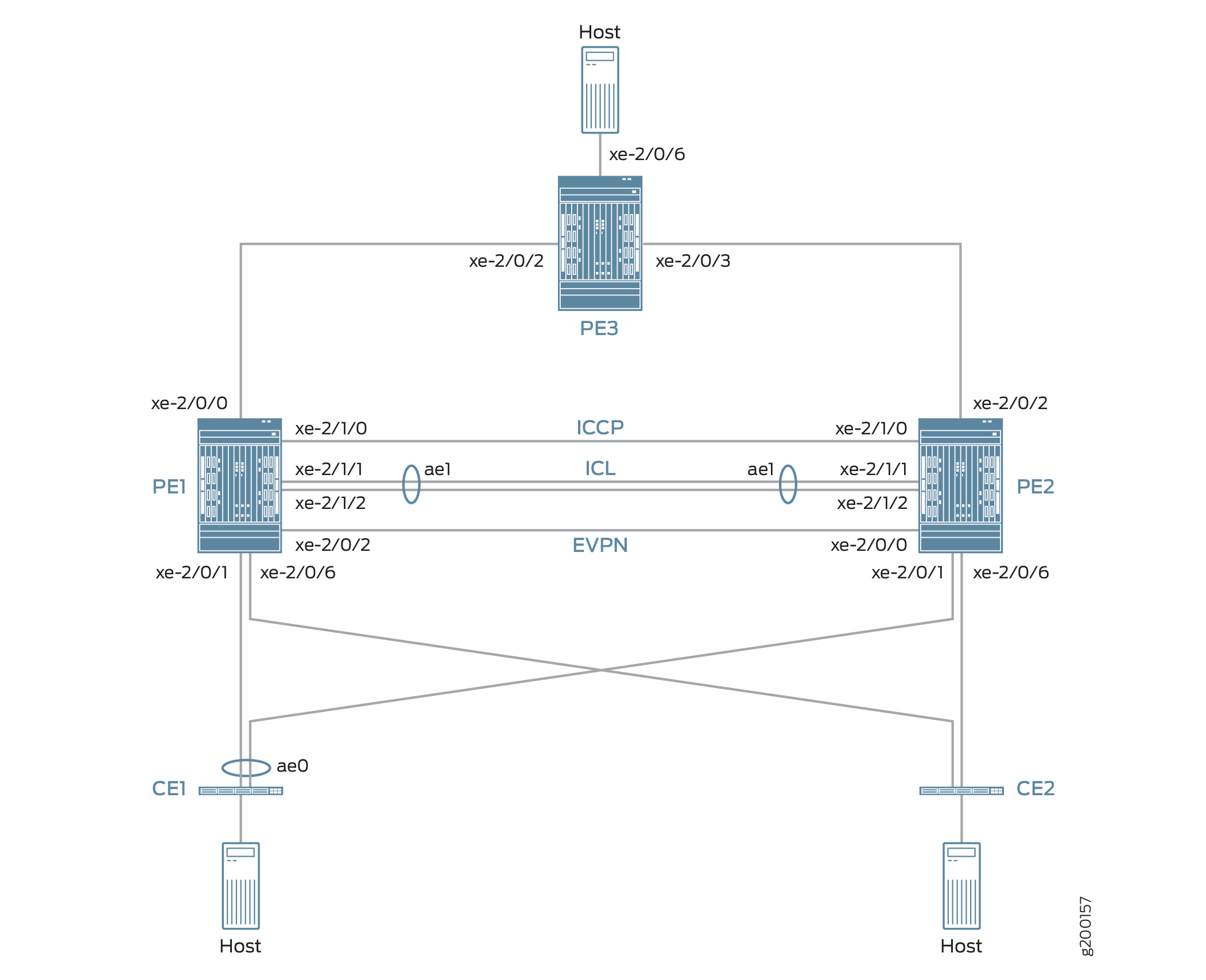
The topology in Figure 1 also includes CE devices CE1 and CE2, which are both multihomed to each PE device. The links between CE1 and the two PE devices are bundled as an aggregated Ethernet interface on which MC-LAG in active-active mode is configured.
The topology in Figure 1 also includes PE3 at the edge of an MPLS network. PE3 functions as the gateway between the MC-LAG network and either a data center or a geographically distributed campus network. PE1, PE2, and PE3 run EVPN, which enables hosts in the MC-LAG network to communicate with hosts in the data center or other campus network by way of an intervening MPLS network.
From the perspective of the EVPN-MPLS interworking feature, PE3 functions solely as an EVPN BGP peer, and PE1 and PE2 in the MC-LAG topology have dual roles:
MC-LAG peers in the MC-LAG network.
EVPN BGP peers in the EVPN-MPLS network.
Because of the dual roles, PE1 and PE2 are configured with MC-LAG, EVPN, BGP, and MPLS attributes.
Table 1 outlines key MC-LAG and EVPN (BGP and MPLS) attributes configured on PE1, PE2, and PE3.
Key Attributes |
PE1 |
PE2 |
PE3 |
|---|---|---|---|
MC-LAG Attributes |
|||
Interfaces |
ICL: aggregated Ethernet interface ae1, which is comprised of xe-2/1/1 and xe-2/1/2 ICCP: xe-2/1/0 |
ICL: aggregated Ethernet interface ae1, which is comprised of xe-2/1/1 and xe-2/1/2 ICCP: xe-2/1/0 |
Not applicable |
EVPN-MPLS |
|||
Interfaces |
Connection to PE3: xe-2/0/0 Connection to PE2: xe-2/0/2 |
Connection to PE3: xe-2/0/2 Connection to PE1: xe-2/0/0 |
Connection to PE1: xe-2/0/2 Connection to PE2: xe-2/0/3 |
IP addresses |
BGP peer address: 198.51.100.1 |
BGP peer address: 198.51.100.2 |
BGP peer address: 198.51.100.3 |
Autonomous system |
65000 |
65000 |
65000 |
Virtual switch routing instances |
evpn1, evpn2, evpn3 |
evpn1, evpn2, evpn3 |
evpn1, evpn2, evpn3 |
Note the following about the EVPN-MPLS interworking feature and its configuration:
You must configure Ethernet segment identifiers (ESIs) on the dual-homed interfaces in the MC-LAG topology. The ESIs enable EVPN to identify the dual-homed interfaces.
The only type of routing instance that is supported is the virtual switch instance (
set routing-instances name instance-type virtual-switch).On the MC-LAG peers, you must include the
bgp-peerconfiguration statement in the[edit routing-instances name protocols evpn mclag]hierarchy level. This configuration statement enables the interworking of EVPN-MPLS with MC-LAG on the MC-LAG peers.Address Resolution Protocol (ARP) suppression is not supported.
PE1 and PE2 Configuration
To configure PE1 and PE2, perform these tasks:
- CLI Quick Configuration
- PE1: Configuring MC-LAG
- PE1: Configuring EVPN-MPLS
- PE2: Configuring MC-LAG
- PE2: Configuring EVPN-MPLS
CLI Quick Configuration
PE1: MC-LAG Configuration
set chassis aggregated-devices ethernet device-count 3
set interfaces xe-2/0/1 gigether-options 802.3ad ae0
set interfaces ae0 flexible-vlan-tagging
set interfaces ae0 encapsulation flexible-ethernet-services
set interfaces ae0 aggregated-ether-options lacp active
set interfaces ae0 aggregated-ether-options lacp periodic fast
set interfaces ae0 aggregated-ether-options lacp system-id 00:00:11:11:11:11
set interfaces ae0 aggregated-ether-options lacp admin-key 1
set interfaces ae0 aggregated-ether-options mc-ae mc-ae-id 1
set interfaces ae0 aggregated-ether-options mc-ae redundancy-group 2
set interfaces ae0 aggregated-ether-options mc-ae chassis-id 0
set interfaces ae0 aggregated-ether-options mc-ae mode active-active
set interfaces ae0 aggregated-ether-options mc-ae status-control active
set interfaces ae0 unit 1 esi 00:11:22:33:44:55:66:77:88:99
set interfaces ae0 unit 1 esi all-active
set interfaces ae0 unit 1 family ethernet-switching interface-mode trunk
set interfaces ae0 unit 1 family ethernet-switching vlan members 1
set interfaces ae0 unit 2 esi 00:11:11:11:11:11:11:11:11:11
set interfaces ae0 unit 2 esi all-active
set interfaces ae0 unit 2 family ethernet-switching interface-mode trunk
set interfaces ae0 unit 2 family ethernet-switching vlan members 2
set interfaces ae0 unit 3 esi 00:11:22:22:22:22:22:22:22:22
set interfaces ae0 unit 3 esi all-active
set interfaces ae0 unit 3 family ethernet-switching interface-mode trunk
set interfaces ae0 unit 3 family ethernet-switching vlan members 3
set interfaces xe-2/0/6 enable
set interfaces xe-2/0/6 flexible-vlan-tagging
set interfaces xe-2/0/6 encapsulation flexible-ethernet-services
set interfaces xe-2/0/6 unit 1 family ethernet-switching interface-mode trunk
set interfaces xe-2/0/6 unit 1 family ethernet-switching vlan members 1
set interfaces xe-2/0/6 unit 2 family ethernet-switching interface-mode trunk
set interfaces xe-2/0/6 unit 2 family ethernet-switching vlan members 2
set interfaces xe-2/0/6 unit 3 family ethernet-switching interface-mode trunk
set interfaces xe-2/0/6 unit 3 family ethernet-switching vlan members 3
set interfaces xe-2/1/0 unit 0 family inet address 203.0.113.1/24
set interfaces xe-2/1/1 gigether-options 802.3ad ae1
set interfaces xe-2/1/2 gigether-options 802.3ad ae1
set interfaces ae1 flexible-vlan-tagging
set interfaces ae1 encapsulation flexible-ethernet-services
set interfaces ae1 aggregated-ether-options lacp active
set interfaces ae1 unit 1 family ethernet-switching interface-mode trunk
set interfaces ae1 unit 1 family ethernet-switching vlan members 1
set interfaces ae1 unit 2 family ethernet-switching interface-mode trunk
set interfaces ae1 unit 2 family ethernet-switching vlan members 2
set interfaces ae1 unit 3 family ethernet-switching interface-mode trunk
set interfaces ae1 unit 3 family ethernet-switching vlan members 3
set multi-chassis multi-chassis-protection 203.0.113.2 interface ae1
set protocols iccp local-ip-addr 203.0.113.1
set protocols iccp peer 203.0.113.2 session-establishment-hold-time 600
set protocols iccp peer 203.0.113.2 redundancy-group-id-list 2
set protocols iccp peer 203.0.113.2 liveness-detection minimum-interval 10000
set protocols iccp peer 203.0.113.2 liveness-detection multiplier 3
PE1: EVPN-MPLS Configuration
set interfaces lo0 unit 0 family inet address 198.51.100.1/32 primary
set interfaces xe-2/0/0 unit 0 family inet address 192.0.2.2/24
set interfaces xe-2/0/0 unit 0 family mpls
set interfaces xe-2/0/2 unit 0 family inet address 192.0.2.111/24
set interfaces xe-2/0/2 unit 0 family mpls
set interfaces irb unit 1 family inet address 10.2.1.1/24 virtual-gateway-address 10.2.1.254
set interfaces irb unit 2 family inet address 10.2.2.1/24 virtual-gateway-address 10.2.2.254
set interfaces irb unit 3 family inet address 10.2.3.1/24 virtual-gateway-address 10.2.3.254
set routing-options router-id 198.51.100.1
set routing-options autonomous-system 65000
set routing-options forwarding-table export evpn-pplb
set protocols mpls interface xe-2/0/0.0
set protocols mpls interface xe-2/0/2.0
set protocols bgp group evpn type internal
set protocols bgp group evpn local-address 198.51.100.1
set protocols bgp group evpn family evpn signaling
set protocols bgp group evpn local-as 65000
set protocols bgp group evpn neighbor 198.51.100.2
set protocols bgp group evpn neighbor 198.51.100.3
set protocols ospf area 0.0.0.0 interface lo0.0
set protocols ospf area 0.0.0.0 interface xe-2/0/0.0
set protocols ospf area 0.0.0.0 interface xe-2/0/2.0
set protocols ldp interface xe-2/0/0.0
set protocols ldp interface xe-2/0/2.0
set protocols ldp interface lo0.0
set policy-options policy-statement evpn-pplb from protocol evpn
set policy-options policy-statement evpn-pplb then load-balance per-packet
set routing-instances evpn1 instance-type virtual-switch
set routing-instances evpn1 interface xe-2/0/6.1
set routing-instances evpn1 interface ae0.1
set routing-instances evpn1 interface ae1.1
set routing-instances evpn1 route-distinguisher 1:10
set routing-instances evpn1 vrf-target target:1:5
set routing-instances evpn1 protocols evpn extended-vlan-list 1
set routing-instances evpn1 protocols evpn mclag bgp-peer 198.51.100.2
set routing-instances evpn1 switch-options service-id 1
set routing-instances evpn1 vlans v1 vlan-id 1
set routing-instances evpn1 vlans v1 l3-interface irb.1
set routing-instances evpn2 instance-type virtual-switch
set routing-instances evpn2 interface xe-2/0/6.2
set routing-instances evpn2 interface ae0.2
set routing-instances evpn2 interface ae1.2
set routing-instances evpn2 route-distinguisher 1:20
set routing-instances evpn2 vrf-target target:1:6
set routing-instances evpn2 protocols evpn extended-vlan-list 2
set routing-instances evpn2 protocols evpn mclag bgp-peer 198.51.100.2
set routing-instances evpn2 switch-options service-id 2
set routing-instances evpn2 vlans v1 vlan-id 2
set routing-instances evpn2 vlans v1 l3-interface irb.2
set routing-instances evpn3 instance-type virtual-switch
set routing-instances evpn3 interface xe-2/0/6.3
set routing-instances evpn3 interface ae0.3
set routing-instances evpn3 interface ae1.3
set routing-instances evpn3 route-distinguisher 1:30
set routing-instances evpn3 vrf-target target:1:7
set routing-instances evpn3 protocols evpn extended-vlan-list 3
set routing-instances evpn3 protocols evpn mclag bgp-peer 198.51.100.2
set routing-instances evpn3 switch-options service-id 3
set routing-instances evpn3 vlans v1 vlan-id 3
set routing-instances evpn3 vlans v1 l3-interface irb.3
PE2: MC-LAG Configuration
set chassis aggregated-devices ethernet device-count 3
set interfaces xe-2/0/1 gigether-options 802.3ad ae0
set interfaces xe-2/0/6 enable
set interfaces xe-2/0/6 flexible-vlan-tagging
set interfaces xe-2/0/6 encapsulation flexible-ethernet-services
set interfaces xe-2/0/6 unit 1 family ethernet-switching interface-mode trunk
set interfaces xe-2/0/6 unit 1 family ethernet-switching vlan members 1
set interfaces xe-2/0/6 unit 2 family ethernet-switching interface-mode trunk
set interfaces xe-2/0/6 unit 2 family ethernet-switching vlan members 2
set interfaces xe-2/0/6 unit 3 family ethernet-switching interface-mode trunk
set interfaces xe-2/0/6 unit 3 family ethernet-switching vlan members 3
set interfaces xe-2/1/0 unit 0 family inet address 203.0.113.2/24
set interfaces xe-2/1/1 gigether-options 802.3ad ae1
set interfaces xe-2/1/2 gigether-options 802.3ad ae1
set interfaces ae0 flexible-vlan-tagging
set interfaces ae0 encapsulation flexible-ethernet-services
set interfaces ae0 aggregated-ether-options lacp active
set interfaces ae0 aggregated-ether-options lacp periodic fast
set interfaces ae0 aggregated-ether-options lacp system-id 00:00:11:11:11:11
set interfaces ae0 aggregated-ether-options lacp admin-key 1
set interfaces ae0 aggregated-ether-options mc-ae mc-ae-id 1
set interfaces ae0 aggregated-ether-options mc-ae redundancy-group 2
set interfaces ae0 aggregated-ether-options mc-ae chassis-id 1
set interfaces ae0 aggregated-ether-options mc-ae mode active-active
set interfaces ae0 aggregated-ether-options mc-ae status-control standby
set interfaces ae0 unit 1 esi 00:11:22:33:44:55:66:77:88:99
set interfaces ae0 unit 1 esi all-active
set interfaces ae0 unit 1 family ethernet-switching interface-mode trunk
set interfaces ae0 unit 1 family ethernet-switching vlan members 1
set interfaces ae0 unit 2 esi 00:11:11:11:11:11:11:11:11:11
set interfaces ae0 unit 2 esi all-active
set interfaces ae0 unit 2 family ethernet-switching interface-mode trunk
set interfaces ae0 unit 2 family ethernet-switching vlan members 2
set interfaces ae0 unit 3 esi 00:11:22:22:22:22:22:22:22:22
set interfaces ae0 unit 3 esi all-active
set interfaces ae0 unit 3 family ethernet-switching interface-mode trunk
set interfaces ae0 unit 3 family ethernet-switching vlan members 3
set interfaces ae1 flexible-vlan-tagging
set interfaces ae1 encapsulation flexible-ethernet-services
set interfaces ae1 aggregated-ether-options lacp active
set interfaces ae1 unit 1 family ethernet-switching interface-mode trunk
set interfaces ae1 unit 1 family ethernet-switching vlan members 1
set interfaces ae1 unit 2 family ethernet-switching interface-mode trunk
set interfaces ae1 unit 2 family ethernet-switching vlan members 2
set interfaces ae1 unit 3 family ethernet-switching interface-mode trunk
set interfaces ae1 unit 3 family ethernet-switching vlan members 3
set multi-chassis multi-chassis-protection 203.0.113.1 interface ae1
set protocols iccp local-ip-addr 203.0.113.2
set protocols iccp peer 203.0.113.1 session-establishment-hold-time 600
set protocols iccp peer 203.0.113.1 redundancy-group-id-list 2
set protocols iccp peer 203.0.113.1 liveness-detection minimum-interval 10000
set protocols iccp peer 203.0.113.1 liveness-detection multiplier 3
PE2: EVPN-MPLS Configuration
set interfaces xe-2/0/0 unit 0 family inet address 192.0.2.222/24
set interfaces xe-2/0/0 unit 0 family mpls
set interfaces xe-2/0/2 unit 0 family inet address 192.0.2.22/24
set interfaces xe-2/0/2 unit 0 family mpls
set interfaces lo0 unit 0 family inet address 198.51.100.2/32 primary
set interfaces irb unit 1 family inet address 10.2.1.2/24 virtual-gateway-address 10.2.1.254
set interfaces irb unit 2 family inet address 10.2.2.2/24 virtual-gateway-address 10.2.2.254
set interfaces irb unit 3 family inet address 10.2.3.2/24 virtual-gateway-address 10.2.3.254
set routing-options router-id 198.51.100.2
set routing-options autonomous-system 65000
set routing-options forwarding-table export evpn-pplb
set protocols mpls interface xe-2/0/2.0
set protocols mpls interface xe-2/0/0.0
set protocols bgp group evpn type internal
set protocols bgp group evpn local-address 198.51.100.2
set protocols bgp group evpn family evpn signaling
set protocols bgp group evpn local-as 65000
set protocols bgp group evpn neighbor 198.51.100.1
set protocols bgp group evpn neighbor 198.51.100.3
set protocols ospf area 0.0.0.0 interface lo0.0
set protocols ospf area 0.0.0.0 interface xe-2/0/0.0
set protocols ospf area 0.0.0.0 interface xe-2/0/2.0
set protocols ldp interface xe-2/0/0.0
set protocols ldp interface xe-2/0/2.0
set protocols ldp interface lo0.0
set policy-options policy-statement evpn-pplb from protocol evpn
set policy-options policy-statement evpn-pplb then load-balance per-packet
set routing-instances evpn1 instance-type virtual-switch
set routing-instances evpn1 interface xe-2/0/6.1
set routing-instances evpn1 interface ae0.1
set routing-instances evpn1 interface ae1.1
set routing-instances evpn1 route-distinguisher 1:11
set routing-instances evpn1 vrf-target target:1:5
set routing-instances evpn1 protocols evpn extended-vlan-list 1
set routing-instances evpn1 protocols evpn mclag bgp-peer 198.51.100.1
set routing-instances evpn1 switch-options service-id 1
set routing-instances evpn1 vlans v1 vlan-id 1
set routing-instances evpn1 vlans v1 l3-interface irb.1
set routing-instances evpn2 instance-type virtual-switch
set routing-instances evpn2 interface xe-2/0/6.2
set routing-instances evpn2 interface ae0.2
set routing-instances evpn2 interface ae1.2
set routing-instances evpn2 route-distinguisher 1:21
set routing-instances evpn2 vrf-target target:1:6
set routing-instances evpn2 protocols evpn extended-vlan-list 2
set routing-instances evpn2 protocols evpn mclag bgp-peer 198.51.100.1
set routing-instances evpn2 switch-options service-id 2
set routing-instances evpn2 vlans v1 vlan-id 2
set routing-instances evpn2 vlans v1 l3-interface irb.2
set routing-instances evpn3 instance-type virtual-switch
set routing-instances evpn3 interface xe-2/0/6.3
set routing-instances evpn3 interface ae0.3
set routing-instances evpn3 interface ae1.3
set routing-instances evpn3 route-distinguisher 1:31
set routing-instances evpn3 vrf-target target:1:7
set routing-instances evpn3 protocols evpn extended-vlan-list 3
set routing-instances evpn3 protocols evpn mclag bgp-peer 198.51.100.1
set routing-instances evpn3 switch-options service-id 3
set routing-instances evpn3 vlans v1 vlan-id 3
set routing-instances evpn3 vlans v1 l3-interface irb.3
PE1: Configuring MC-LAG
Step-by-Step Procedure
Set the number of aggregated Ethernet interfaces on PE1.
[edit]
user@switch# set chassis aggregated-devices ethernet device-count 3
Configure aggregated Ethernet interface ae0 on interface xe-2/0/1, and configure LACP and MC-LAG on ae0. Divide aggregated Ethernet interface ae0 into three logical interfaces (ae0.1, ae0.2, and ae0.3). For each logical interface, specify an ESI, place the logical interface is in MC-LAG active-active mode, and map the logical interface to a VLAN.
[edit]
user@switch# set interfaces xe-2/0/1 gigether-options 802.3ad ae0
user@switch# set interfaces ae0 flexible-vlan-tagging
user@switch# set interfaces ae0 encapsulation flexible-ethernet-services
user@switch# set interfaces ae0 aggregated-ether-options lacp active
user@switch# set interfaces ae0 aggregated-ether-options lacp periodic fast
user@switch# set interfaces ae0 aggregated-ether-options lacp system-id 00:00:11:11:11:11
user@switch# set interfaces ae0 aggregated-ether-options lacp admin-key 1
user@switch# set interfaces ae0 aggregated-ether-options mc-ae mc-ae-id 1
user@switch# set interfaces ae0 aggregated-ether-options mc-ae redundancy-group 2
user@switch# set interfaces ae0 aggregated-ether-options mc-ae chassis-id 0
user@switch# set interfaces ae0 aggregated-ether-options mc-ae mode active-active
user@switch# set interfaces ae0 aggregated-ether-options mc-ae status-control active
user@switch# set interfaces ae0 unit 1 esi 00:11:22:33:44:55:66:77:88:99
user@switch# set interfaces ae0 unit 1 esi all-active
user@switch# set interfaces ae0 unit 1 family ethernet-switching interface-mode trunk
user@switch# set interfaces ae0 unit 1 family ethernet-switching vlan members 1
user@switch# set interfaces ae0 unit 2 esi 00:11:11:11:11:11:11:11:11:11
user@switch# set interfaces ae0 unit 2 esi all-active
user@switch# set interfaces ae0 unit 2 family ethernet-switching interface-mode trunk
user@switch# set interfaces ae0 unit 2 family ethernet-switching vlan members 2
user@switch# set interfaces ae0 unit 3 esi 00:11:22:22:22:22:22:22:22:22
user@switch# set interfaces ae0 unit 3 esi all-active
user@switch# set interfaces ae0 unit 3 family ethernet-switching interface-mode trunk
user@switch# set interfaces ae0 unit 3 family ethernet-switching vlan members 3
Configure physical interface xe-2/0/6, and divide it into three logical interfaces (xe-2/0/6.1, xe-2/0/6.2, and xe-2/0/6.3). Map each logical interface to a VLAN.
[edit]
user@switch# set interfaces xe-2/0/6 enable
user@switch# set interfaces xe-2/0/6 flexible-vlan-tagging
user@switch# set interfaces xe-2/0/6 encapsulation flexible-ethernet-services
user@switch# set interfaces xe-2/0/6 unit 1 family ethernet-switching interface-mode trunk
user@switch# set interfaces xe-2/0/6 unit 1 family ethernet-switching vlan members 1
user@switch# set interfaces xe-2/0/6 unit 2 family ethernet-switching interface-mode trunk
user@switch# set interfaces xe-2/0/6 unit 2 family ethernet-switching vlan members 2
user@switch# set interfaces xe-2/0/6 unit 3 family ethernet-switching interface-mode trunk
user@switch# set interfaces xe-2/0/6 unit 3 family ethernet-switching vlan members 3
Configure physical interface xe-2/1/0 as a Layer 3 interface, on which you configure ICCP. Specify the interface with the IP address of 203.0.113.2 on PE2 as the ICCP peer to PE1.
[edit]
user@switch# set interfaces xe-2/1/0 unit 0 family inet address 203.0.113.1/24
user@switch# set protocols iccp local-ip-addr 203.0.113.1
user@switch# set protocols iccp peer 203.0.113.2 session-establishment-hold-time 600
user@switch# set protocols iccp peer 203.0.113.2 redundancy-group-id-list 2
user@switch# set protocols iccp peer 203.0.113.2 liveness-detection minimum-interval 10000
user@switch# set protocols iccp peer 203.0.113.2 liveness-detection multiplier 3
Configure aggregated Ethernet interface ae1 on interfaces xe-2/1/1 and xe-2/1/2, and configure LACP on ae1. Divide aggregated Ethernet interface ae1 into three logical interfaces (ae1.1, ae1.2, and ae1.3), and map each logical interface to a VLAN. Specify ae1 as the multichassis protection link between PE1 and PE2.
[edit]
user@switch# set interfaces xe-2/1/1 gigether-options 802.3ad ae1
user@switch# set interfaces xe-2/1/2 gigether-options 802.3ad ae1
user@switch# set interfaces ae1 flexible-vlan-tagging
user@switch# set interfaces ae1 encapsulation flexible-ethernet-services
user@switch# set interfaces ae1 aggregated-ether-options lacp active
user@switch# set interfaces ae1 unit 1 family ethernet-switching interface-mode trunk
user@switch# set interfaces ae1 unit 1 family ethernet-switching vlan members 1
user@switch# set interfaces ae1 unit 2 family ethernet-switching interface-mode trunk
user@switch# set interfaces ae1 unit 2 family ethernet-switching vlan members 2
user@switch# set interfaces ae1 unit 3 family ethernet-switching interface-mode trunk
user@switch# set interfaces ae1 unit 3 family ethernet-switching vlan members 3
user@switch# set multi-chassis multi-chassis-protection 203.0.113.2 interface ae1
PE1: Configuring EVPN-MPLS
Step-by-Step Procedure
Configure the loopback interface, and the interfaces connected to the other PE devices.
[edit]
user@switch# set interfaces lo0 unit 0 family inet address 198.51.100.1/32 primary
user@switch# set interfaces xe-2/0/0 unit 0 family inet address 192.0.2.2/24
user@switch# set interfaces xe-2/0/0 unit 0 family mpls
user@switch# set interfaces xe-2/0/2 unit 0 family inet address 192.0.2.111/24
user@switch# set interfaces xe-2/0/2 unit 0 family mpls
Configure IRB interfaces irb.1, irb.2, and irb.3.
[edit]
user@switch# set interfaces irb unit 1 family inet address 10.2.1.1/24 virtual-gateway-address 10.2.1.254
user@switch# set interfaces irb unit 2 family inet address 10.2.2.1/24 virtual-gateway-address 10.2.2.254
user@switch# set interfaces irb unit 3 family inet address 10.2.3.1/24 virtual-gateway-address 10.2.3.254
Assign a router ID and the autonomous system in which PE1, PE2, and PE3 reside.
[edit]
user@switch# set routing-options router-id 198.51.100.1
user@switch# set routing-options autonomous-system 65000
Enable per-packet load-balancing for EVPN routes when EVPN multihoming active-active mode is used.
[edit]
user@switch# set routing-options forwarding-table export evpn-pplb
user@switch# set policy-options policy-statement evpn-pplb from protocol evpn
user@switch# set policy-options policy-statement evpn-pplb then load-balance per-packet
Enable MPLS on interfaces xe-2/0/0.0 and xe-2/0/2.0.
[edit]
user@switch# set protocols mpls interface xe-2/0/0.0
user@switch# set protocols mpls interface xe-2/0/2.0
Configure an IBGP overlay that includes PE1, PE2, and PE3.
[edit]
user@switch# set protocols bgp group evpn type internal
user@switch# set protocols bgp group evpn local-address 198.51.100.1
user@switch# set protocols bgp group evpn family evpn signaling
user@switch# set protocols bgp group evpn local-as 65000
user@switch# set protocols bgp group evpn neighbor 198.51.100.2
user@switch# set protocols bgp group evpn neighbor 198.51.100.3
Configure OSPF as the internal routing protocol for EVPN by specifying an area ID and interfaces on which EVPN-MPLS is enabled.
[edit]
user@switch# set protocols ospf area 0.0.0.0 interface lo0.0
user@switch# set protocols ospf area 0.0.0.0 interface xe-2/0/0.0
user@switch# set protocols ospf area 0.0.0.0 interface xe-2/0/2.0
Configure the Label Distribution Protocol (LDP) on the loopback interface and the interfaces on which EVPN-MPLS is enabled.
[edit]
user@switch# set protocols ldp interface lo0.0
user@switch# set protocols ldp interface xe-2/0/0.0
user@switch# set protocols ldp interface xe-2/0/2.0
Configure virtual switch routing instances for VLAN v1, which is assigned VLAN IDs of 1, 2, and 3, and include the interfaces and other entities associated with the VLAN.
[edit]
user@switch# set routing-instances evpn1 instance-type virtual-switch
user@switch# set routing-instances evpn1 interface xe-2/0/6.1
user@switch# set routing-instances evpn1 interface ae0.1
user@switch# set routing-instances evpn1 interface ae1.1
user@switch# set routing-instances evpn1 route-distinguisher 1:10
user@switch# set routing-instances evpn1 vrf-target target:1:5
user@switch# set routing-instances evpn1 protocols evpn extended-vlan-list 1
user@switch# set routing-instances evpn1 protocols evpn mclag bgp-peer 198.51.100.2
user@switch# set routing-instances evpn1 switch-options service-id 1
user@switch# set routing-instances evpn1 vlans v1 vlan-id 1
user@switch# set routing-instances evpn1 vlans v1 l3-interface irb.1
user@switch# set routing-instances evpn2 instance-type virtual-switch
user@switch# set routing-instances evpn2 interface xe-2/0/6.2
user@switch# set routing-instances evpn2 interface ae0.2
user@switch# set routing-instances evpn2 interface ae1.2
user@switch# set routing-instances evpn2 route-distinguisher 1:20
user@switch# set routing-instances evpn2 vrf-target target:1:6
user@switch# set routing-instances evpn2 protocols evpn extended-vlan-list 2
user@switch# set routing-instances evpn2 protocols evpn mclag bgp-peer 198.51.100.2
user@switch# set routing-instances evpn2 switch-options service-id 2
user@switch# set routing-instances evpn2 vlans v1 vlan-id 2
user@switch# set routing-instances evpn2 vlans v1 l3-interface irb.2
user@switch# set routing-instances evpn3 instance-type virtual-switch
user@switch# set routing-instances evpn3 interface xe-2/0/6.3
user@switch# set routing-instances evpn3 interface ae0.3
user@switch# set routing-instances evpn3 interface ae1.3
user@switch# set routing-instances evpn3 route-distinguisher 1:30
user@switch# set routing-instances evpn3 vrf-target target:1:7
user@switch# set routing-instances evpn3 protocols evpn extended-vlan-list 3
user@switch# set routing-instances evpn3 protocols evpn mclag bgp-peer 198.51.100.2
user@switch# set routing-instances evpn3 switch-options service-id 3
user@switch# set routing-instances evpn3 vlans v1 vlan-id 3
user@switch# set routing-instances evpn3 vlans v1 l3-interface irb.3
PE2: Configuring MC-LAG
Step-by-Step Procedure
Set the number of aggregated Ethernet interfaces on PE2.
[edit]
user@switch# set chassis aggregated-devices ethernet device-count 3
Configure aggregated Ethernet interface ae0 on interface xe-2/0/1, and configure LACP and MC-LAG on ae0. Divide aggregated Ethernet interface ae0 into three logical interfaces (ae0.1, ae0.2, and ae0.3). For each logical interface, specify an ESI, place the logical interface is in MC-LAG active-active mode, and map the logical interface to a VLAN.
[edit]
user@switch# set interfaces xe-2/0/1 gigether-options 802.3ad ae0
user@switch# set interfaces ae0 flexible-vlan-tagging
user@switch# set interfaces ae0 encapsulation flexible-ethernet-services
user@switch# set interfaces ae0 aggregated-ether-options lacp active
user@switch# set interfaces ae0 aggregated-ether-options lacp periodic fast
user@switch# set interfaces ae0 aggregated-ether-options lacp system-id 00:00:11:11:11:11
user@switch# set interfaces ae0 aggregated-ether-options lacp admin-key 1
user@switch# set interfaces ae0 aggregated-ether-options mc-ae mc-ae-id 1
user@switch# set interfaces ae0 aggregated-ether-options mc-ae redundancy-group 2
user@switch# set interfaces ae0 aggregated-ether-options mc-ae chassis-id 1
user@switch# set interfaces ae0 aggregated-ether-options mc-ae mode active-active
user@switch# set interfaces ae0 aggregated-ether-options mc-ae status-control standby
user@switch# set interfaces ae0 unit 1 esi 00:11:22:33:44:55:66:77:88:99
user@switch# set interfaces ae0 unit 1 esi all-active
user@switch# set interfaces ae0 unit 1 family ethernet-switching interface-mode trunk
user@switch# set interfaces ae0 unit 1 family ethernet-switching vlan members 1
user@switch# set interfaces ae0 unit 2 esi 00:11:11:11:11:11:11:11:11:11
user@switch# set interfaces ae0 unit 2 esi all-active
user@switch# set interfaces ae0 unit 2 family ethernet-switching interface-mode trunk
user@switch# set interfaces ae0 unit 2 family ethernet-switching vlan members 2
user@switch# set interfaces ae0 unit 3 esi 00:11:22:22:22:22:22:22:22:22
user@switch# set interfaces ae0 unit 3 esi all-active
user@switch# set interfaces ae0 unit 3 family ethernet-switching interface-mode trunk
user@switch# set interfaces ae0 unit 3 family ethernet-switching vlan members 3
Configure physical interface xe-2/0/6, and divide it into three logical interfaces (xe-2/0/6.1, xe-2/0/6.2, and xe-2/0/6.3). Map each logical interface to a VLAN.
[edit]
set interfaces xe-2/0/6 enable
set interfaces xe-2/0/6 flexible-vlan-tagging
set interfaces xe-2/0/6 encapsulation flexible-ethernet-services
set interfaces xe-2/0/6 unit 1 family ethernet-switching interface-mode trunk
set interfaces xe-2/0/6 unit 1 family ethernet-switching vlan members 1
set interfaces xe-2/0/6 unit 2 family ethernet-switching interface-mode trunk
set interfaces xe-2/0/6 unit 2 family ethernet-switching vlan members 2
set interfaces xe-2/0/6 unit 3 family ethernet-switching interface-mode trunk
set interfaces xe-2/0/6 unit 3 family ethernet-switching vlan members 3
Configure physical interface xe-2/1/0 as a Layer 3 interface, on which you configure ICCP. Specify the interface with the IP address of 203.0.113.1 on PE1 as the ICCP peer to PE2.
[edit]
set interfaces xe-2/1/0 unit 0 family inet address 203.0.113.2/24
set protocols iccp local-ip-addr 203.0.113.2
set protocols iccp peer 203.0.113.1 session-establishment-hold-time 600
set protocols iccp peer 203.0.113.1 redundancy-group-id-list 2
set protocols iccp peer 203.0.113.1 liveness-detection minimum-interval 10000
set protocols iccp peer 203.0.113.1 liveness-detection multiplier 3
Configure aggregated Ethernet interface ae1 on interfaces xe-2/1/1 and xe-2/1/2, and configure LACP on ae1. Divide aggregated Ethernet interface ae1 into three logical interfaces (ae1.1, ae1.2, and ae1.3), and map each logical interface to a VLAN. Specify ae1 as the multichassis protection link between PE1 and PE2.
[edit]
set interfaces xe-2/1/1 gigether-options 802.3ad ae1
set interfaces xe-2/1/2 gigether-options 802.3ad ae1
set interfaces ae1 flexible-vlan-tagging
set interfaces ae1 encapsulation flexible-ethernet-services
set interfaces ae1 aggregated-ether-options lacp active
set interfaces ae1 unit 1 family ethernet-switching interface-mode trunk
set interfaces ae1 unit 1 family ethernet-switching vlan members 1
set interfaces ae1 unit 2 family ethernet-switching interface-mode trunk
set interfaces ae1 unit 2 family ethernet-switching vlan members 2
set interfaces ae1 unit 3 family ethernet-switching interface-mode trunk
set interfaces ae1 unit 3 family ethernet-switching vlan members 3
set multi-chassis multi-chassis-protection 203.0.113.1 interface ae1
PE2: Configuring EVPN-MPLS
Step-by-Step Procedure
Configure the loopback interface, and the interfaces connected to the other PE devices.
[edit]
user@switch# set interfaces lo0 unit 0 family inet address 198.51.100.2/32 primary
user@switch# set interfaces xe-2/0/0 unit 0 family inet address 192.0.2.222/24
user@switch# set interfaces xe-2/0/0 unit 0 family mpls
user@switch# set interfaces xe-2/0/2 unit 0 family inet address 192.0.2.22/24
user@switch# set interfaces xe-2/0/2 unit 0 family mpls
Configure IRB interfaces irb.1, irb.2, and irb.3.
[edit]
user@switch# set interfaces irb unit 1 family inet address 10.2.1.2/24 virtual-gateway-address 10.2.1.254
user@switch# set interfaces irb unit 2 family inet address 10.2.2.2/24 virtual-gateway-address 10.2.2.254
user@switch# set interfaces irb unit 3 family inet address 10.2.3.2/24 virtual-gateway-address 10.2.3.254
Assign a router ID and the autonomous system in which PE1, PE2, and PE3 reside.
[edit]
user@switch# set routing-options router-id 198.51.100.2
user@switch# set routing-options autonomous-system 65000
Enable per-packet load-balancing for EVPN routes when EVPN multihoming active-active mode is used.
[edit]
user@switch# set routing-options forwarding-table export evpn-pplb
user@switch# set policy-options policy-statement evpn-pplb from protocol evpn
user@switch# set policy-options policy-statement evpn-pplb then load-balance per-packet
Enable MPLS on interfaces xe-2/0/0.0 and xe-2/0/2.0.
[edit]
user@switch# set protocols mpls interface xe-2/0/0.0
user@switch# set protocols mpls interface xe-2/0/2.0
Configure an IBGP overlay that includes PE1, PE2, and PE3.
[edit]
user@switch# set protocols bgp group evpn type internal
user@switch# set protocols bgp group evpn local-address 198.51.100.2
user@switch# set protocols bgp group evpn family evpn signaling
user@switch# set protocols bgp group evpn local-as 65000
user@switch# set protocols bgp group evpn neighbor 198.51.100.1
user@switch# set protocols bgp group evpn neighbor 198.51.100.3
Configure OSPF as the internal routing protocol for EVPN by specifying an area ID and interfaces on which EVPN-MPLS is enabled.
[edit]
user@switch# set protocols ospf area 0.0.0.0 interface lo0.0
user@switch# set protocols ospf area 0.0.0.0 interface xe-2/0/0.0
user@switch# set protocols ospf area 0.0.0.0 interface xe-2/0/2.0
Configure the Label Distribution Protocol (LDP) on the loopback interface and the interfaces on which EVPN-MPLS is enabled.
[edit]
user@switch# set protocols ldp interface lo0.0
user@switch# set protocols ldp interface xe-2/0/0.0
user@switch# set protocols ldp interface xe-2/0/2.0
Configure virtual switch routing instances for VLAN v1, which is assigned VLAN IDs of 1, 2, and 3, and include the interfaces and other entities associated with the VLAN.
[edit]
user@switch# set routing-instances evpn1 instance-type virtual-switch
user@switch# set routing-instances evpn1 interface xe-2/0/6.1
user@switch# set routing-instances evpn1 interface ae0.1
user@switch# set routing-instances evpn1 interface ae1.1
user@switch# set routing-instances evpn1 route-distinguisher 1:11
user@switch# set routing-instances evpn1 vrf-target target:1:5
user@switch# set routing-instances evpn1 protocols evpn extended-vlan-list 1
user@switch# set routing-instances evpn1 protocols evpn mclag bgp-peer 198.51.100.1
user@switch# set routing-instances evpn1 switch-options service-id 1
user@switch# set routing-instances evpn1 vlans v1 vlan-id 1
user@switch# set routing-instances evpn1 vlans v1 l3-interface irb.1
user@switch# set routing-instances evpn2 instance-type virtual-switch
user@switch# set routing-instances evpn2 interface xe-2/0/6.2
user@switch# set routing-instances evpn2 interface ae0.2
user@switch# set routing-instances evpn2 interface ae1.2
user@switch# set routing-instances evpn2 route-distinguisher 1:21
user@switch# set routing-instances evpn2 vrf-target target:1:6
user@switch# set routing-instances evpn2 protocols evpn extended-vlan-list 2
user@switch# set routing-instances evpn2 protocols evpn mclag bgp-peer 198.51.100.1
user@switch# set routing-instances evpn2 switch-options service-id 2
user@switch# set routing-instances evpn2 vlans v1 vlan-id 2
user@switch# set routing-instances evpn2 vlans v1 l3-interface irb.2
user@switch# set routing-instances evpn3 instance-type virtual-switch
user@switch# set routing-instances evpn3 interface xe-2/0/6.3
user@switch# set routing-instances evpn3 interface ae0.3
user@switch# set routing-instances evpn3 interface ae1.3
user@switch# set routing-instances evpn3 route-distinguisher 1:31
user@switch# set routing-instances evpn3 vrf-target target:1:7
user@switch# set routing-instances evpn3 protocols evpn extended-vlan-list 3
user@switch# set routing-instances evpn3 protocols evpn mclag bgp-peer 198.51.100.1
user@switch# set routing-instances evpn3 switch-options service-id 3
user@switch# set routing-instances evpn3 vlans v1 vlan-id 3
user@switch# set routing-instances evpn3 vlans v1 l3-interface irb.3
PE3 Configuration
CLI Quick Configuration
PE3: EVPN-MPLS Configuration
set interfaces lo0 unit 0 family inet address 198.51.100.3/32 primary
set interfaces xe-2/0/2 unit 0 family inet address 192.0.2.1/24
set interfaces xe-2/0/2 unit 0 family mpls
set interfaces xe-2/0/3 unit 0 family inet address 192.0.2.11/24
set interfaces xe-2/0/3 unit 0 family mpls
set interfaces xe-2/0/6 enable
set interfaces xe-2/0/6 flexible-vlan-tagging
set interfaces xe-2/0/6 encapsulation flexible-ethernet-services
set interfaces xe-2/0/6 unit 1 family ethernet-switching interface-mode trunk
set interfaces xe-2/0/6 unit 1 family ethernet-switching vlan members 1
set interfaces xe-2/0/6 unit 2 family ethernet-switching interface-mode trunk
set interfaces xe-2/0/6 unit 2 family ethernet-switching vlan members 2
set interfaces xe-2/0/6 unit 3 family ethernet-switching interface-mode trunk
set interfaces xe-2/0/6 unit 3 family ethernet-switching vlan members 3
set interfaces irb unit 1 family inet address 10.2.1.3/24 virtual-gateway-address 10.2.1.254
set interfaces irb unit 2 family inet address 10.2.2.3/24 virtual-gateway-address 10.2.2.254
set interfaces irb unit 3 family inet address 10.2.3.3/24 virtual-gateway-address 10.2.3.254
set routing-options router-id 198.51.100.3
set routing-options autonomous-system 65000
set routing-options forwarding-table export evpn-pplb
set protocols mpls interface xe-2/0/2.0
set protocols mpls interface xe-2/0/3.0
set protocols bgp group evpn type internal
set protocols bgp group evpn local-address 198.51.100.3
set protocols bgp group evpn family evpn signaling
set protocols bgp group evpn local-as 65000
set protocols bgp group evpn neighbor 198.51.100.1
set protocols bgp group evpn neighbor 198.51.100.2
set protocols ospf area 0.0.0.0 interface lo0.0
set protocols ospf area 0.0.0.0 interface xe-2/0/2.0
set protocols ospf area 0.0.0.0 interface xe-2/0/3.0
set protocols ldp interface lo0.0
set protocols ldp interface xe-2/0/2.0
set protocols ldp interface xe-2/0/3.0
set policy-options policy-statement evpn-pplb from protocol evpn
set policy-options policy-statement evpn-pplb then load-balance per-packet
set routing-instances evpn1 instance-type virtual-switch
set routing-instances evpn1 interface xe-2/0/6.1
set routing-instances evpn1 route-distinguisher 1:12
set routing-instances evpn1 vrf-target target:1:5
set routing-instances evpn1 protocols evpn extended-vlan-list 1
set routing-instances evpn1 switch-options service-id 1
set routing-instances evpn1 vlans v1 vlan-id 1
set routing-instances evpn1 vlans v1 l3-interface irb.1
set routing-instances evpn2 instance-type virtual-switch
set routing-instances evpn2 interface xe-2/0/6.2
set routing-instances evpn2 route-distinguisher 1:22
set routing-instances evpn2 vrf-target target:1:6
set routing-instances evpn2 protocols evpn extended-vlan-list 2
set routing-instances evpn2 switch-options service-id 2
set routing-instances evpn2 vlans v1 vlan-id 2
set routing-instances evpn2 vlans v1 l3-interface irb.2
set routing-instances evpn3 instance-type virtual-switch
set routing-instances evpn3 interface xe-2/0/6.3
set routing-instances evpn3 route-distinguisher 1:32
set routing-instances evpn3 vrf-target target:1:7
set routing-instances evpn3 protocols evpn extended-vlan-list 3
set routing-instances evpn3 switch-options service-id 3
set routing-instances evpn3 vlans v1 vlan-id 3
set routing-instances evpn3 vlans v1 l3-interface irb.3
PE3: Configuring EVPN-MPLS
Step-by-Step Procedure
Configure the loopback interface, and the interfaces connected to the other PE devices.
[edit]
user@switch# set interfaces lo0 unit 0 family inet address 198.51.100.3/32 primary
user@switch# set interfaces xe-2/0/2 unit 0 family inet address 192.0.2.1/24
user@switch# set interfaces xe-2/0/2 unit 0 family mpls
user@switch# set interfaces xe-2/0/3 unit 0 family inet address 192.0.2.11/24
user@switch# set interfaces xe-2/0/3 unit 0 family mpls
Configure interface xe-2/0/6, which is connected to the host.
[edit]
user@switch# set interfaces xe-2/0/6 enable
user@switch# set interfaces xe-2/0/6 flexible-vlan-tagging
user@switch# set interfaces xe-2/0/6 encapsulation flexible-ethernet-services
user@switch# set interfaces xe-2/0/6 unit 1 family ethernet-switching interface-mode trunk
user@switch# set interfaces xe-2/0/6 unit 1 family ethernet-switching vlan members 1
user@switch# set interfaces xe-2/0/6 unit 2 family ethernet-switching interface-mode trunk
user@switch# set interfaces xe-2/0/6 unit 2 family ethernet-switching vlan members 2
user@switch# set interfaces xe-2/0/6 unit 3 family ethernet-switching interface-mode trunk
user@switch# set interfaces xe-2/0/6 unit 3 family ethernet-switching vlan members 3
Configure IRB interfaces irb.1, irb.2, and irb.3.
[edit]
user@switch# set interfaces irb unit 1 family inet address 10.2.1.3/24 virtual-gateway-address 10.2.1.254
user@switch# set interfaces irb unit 2 family inet address 10.2.2.3/24 virtual-gateway-address 10.2.2.254
user@switch# set interfaces irb unit 3 family inet address 10.2.3.3/24 virtual-gateway-address 10.2.3.254
Assign a router ID and the autonomous system in which PE1, PE2, and PE3 reside.
[edit]
user@switch# set routing-options router-id 198.51.100.3
user@switch# set routing-options autonomous-system 65000
Enable per-packet load-balancing for EVPN routes when EVPN multihoming active-active mode is used.
[edit]
user@switch# set routing-options forwarding-table export evpn-pplb
user@switch# set policy-options policy-statement evpn-pplb from protocol evpn
user@switch# set policy-options policy-statement evpn-pplb then load-balance per-packet
Enable MPLS on interfaces xe-2/0/2.0 and xe-2/0/3.0.
[edit]
user@switch# set protocols mpls interface xe-2/0/2.0
user@switch# set protocols mpls interface xe-2/0/3.0
Configure an IBGP overlay that includes PE1, PE2, and PE3.
[edit]
user@switch# set protocols bgp group evpn type internal
user@switch# set protocols bgp group evpn local-address 198.51.100.3
user@switch# set protocols bgp group evpn family evpn signaling
user@switch# set protocols bgp group evpn local-as 65000
user@switch# set protocols bgp group evpn neighbor 198.51.100.1
user@switch# set protocols bgp group evpn neighbor 198.51.100.2
Configure OSPF as the internal routing protocol for EVPN by specifying an area ID and interfaces on which EVPN-MPLS is enabled.
[edit]
user@switch# set protocols ospf area 0.0.0.0 interface lo0.0
user@switch# set protocols ospf area 0.0.0.0 interface xe-2/0/2.0
user@switch# set protocols ospf area 0.0.0.0 interface xe-2/0/3.0
Configure the LDP on the loopback interface and the interfaces on which EVPN-MPLS is enabled.
[edit]
user@switch# set protocols ldp interface lo0.0
user@switch# set protocols ldp interface xe-2/0/2.0
user@switch# set protocols ldp interface xe-2/0/3.0
Configure virtual switch routing instances for VLAN v1, which is assigned VLAN IDs of 1, 2, and 3, and include the interfaces and other entities associated with the VLAN.
[edit]
user@switch# set routing-instances evpn1 instance-type virtual-switch
user@switch# set routing-instances evpn1 interface xe-2/0/6.1
user@switch# set routing-instances evpn1 route-distinguisher 1:12
user@switch# set routing-instances evpn1 vrf-target target:1:5
user@switch# set routing-instances evpn1 protocols evpn extended-vlan-list 1
user@switch# set routing-instances evpn1 switch-options service-id 1
user@switch# set routing-instances evpn1 vlans v1 vlan-id 1
user@switch# set routing-instances evpn1 vlans v1 l3-interface irb.1
user@switch# set routing-instances evpn2 instance-type virtual-switch
user@switch# set routing-instances evpn2 interface xe-2/0/6.2
user@switch# set routing-instances evpn2 route-distinguisher 1:22
user@switch# set routing-instances evpn2 vrf-target target:1:6
user@switch# set routing-instances evpn2 protocols evpn extended-vlan-list 2
user@switch# set routing-instances evpn2 switch-options service-id 2
user@switch# set routing-instances evpn2 vlans v1 vlan-id 2
user@switch# set routing-instances evpn2 vlans v1 l3-interface irb.2
user@switch# set routing-instances evpn3 instance-type virtual-switch
user@switch# set routing-instances evpn3 interface xe-2/0/6.3
user@switch# set routing-instances evpn3 route-distinguisher 1:32
user@switch# set routing-instances evpn3 vrf-target target:1:7
user@switch# set routing-instances evpn3 protocols evpn extended-vlan-list 3
user@switch# set routing-instances evpn3 switch-options service-id 3
user@switch# set routing-instances evpn3 vlans v1 vlan-id 3
user@switch# set routing-instances evpn3 vlans v1 l3-interface irb.3