Backup Liveness Detection on EVPN Dual Homing
By default, spine-and-leaf devices in an EVPN network implement the core isolation feature. When a device loses all of its EVPN BGP peering sessions it triggers the core isolation feature. Using the LACP, the core isolation feature shuts down all L2 ESI LAG interfaces.
In some situations, the core isolation feature produces a favorable outcome. In other situations, the core isolation feature produces an undesired outcome, which you can prevent by disabling it. However, in a dual-homed architecture, disabling the core isolation feature on one or both peers can cause other issues. You can address these issues by configuring node liveness detection along with the default core isolation feature.
Please refer to Feature Explorer for a complete list of the products that support the Backup liveness detection on EVPN dual homed peers feature.
EVPN Core Isolation Configurations
Figure 1 displays an EVPN-VXLAN topology with two spine devices with the default configuration for core isolation. The switches acting as leaf devices are multihomed in active/active mode through ESI-LAG interfaces to the spine devices.
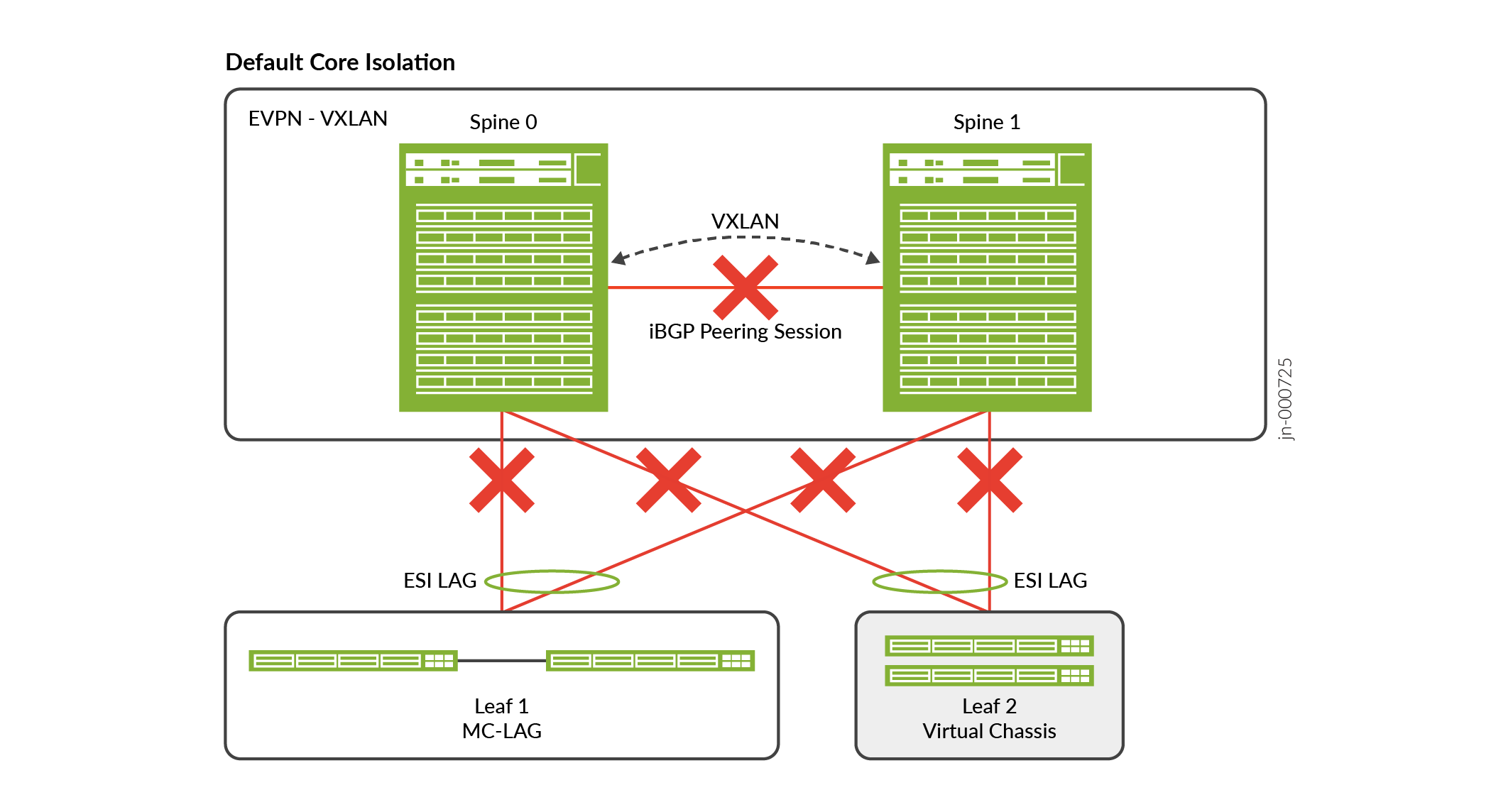
If the link between Spine 0 and Spine 1 goes down, the last established BGP peering session also goes down. The default core isolation feature triggers LACP to set the leaf-facing interfaces on Spines 0 and 1 to standby mode. This causes data traffic to and from both leaf devices to be dropped halting traffic within the data center, which is an undesired outcome.
Figure 2 displays an EVPN-VXLAN topology with two spine devices with
no-core-isolation configured. The switches acting as leaf devices are
multihomed in active/active mode through ESI-LAG interfaces to the spine devices.
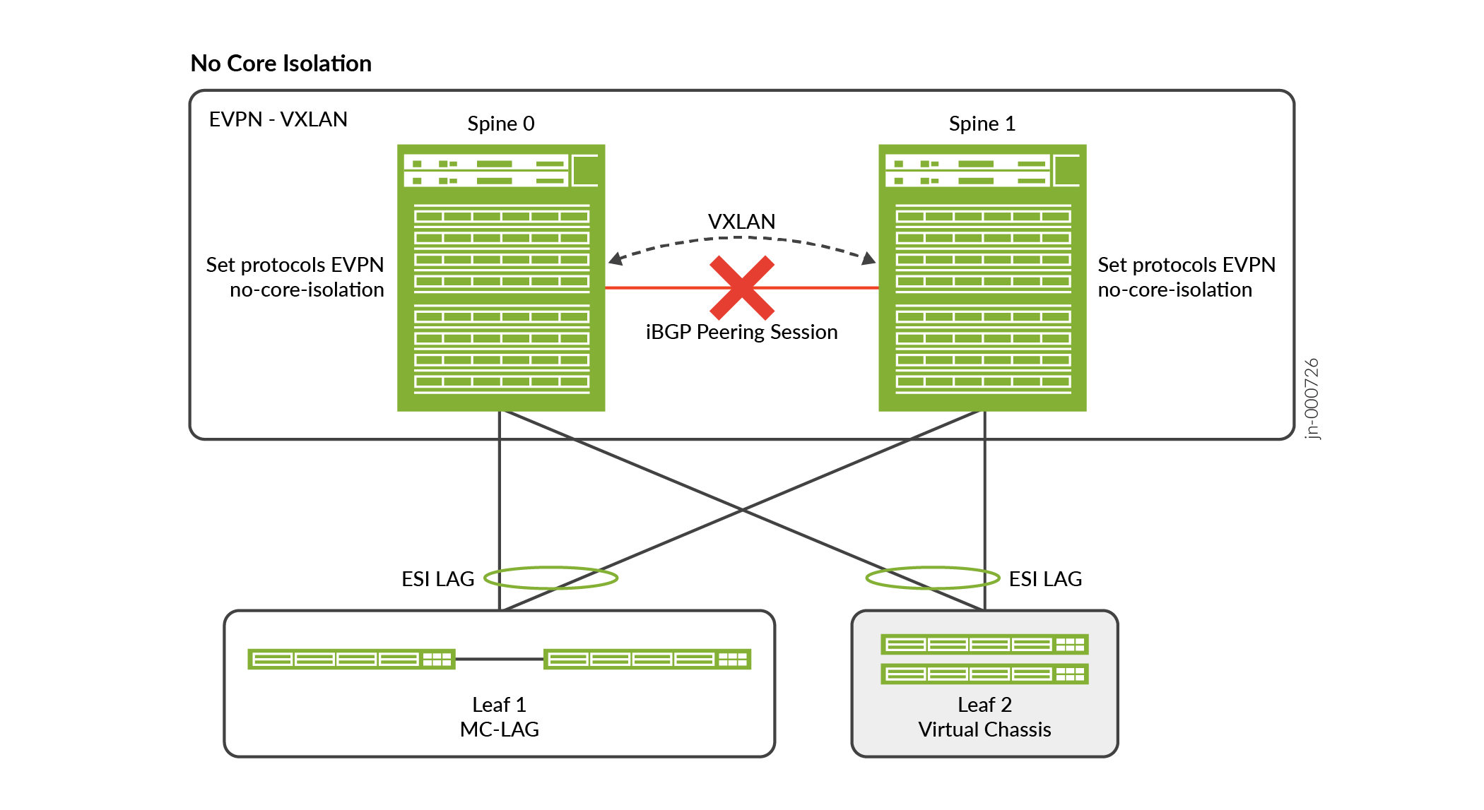
Disabling the core isolation feature could cause the following issues:
-
With
no-core-isolationconfigured on both Spine devices the links to the leaf devices will remain up even when BGP is down. But L3 traffic might fail because ARP/ND resolution will fail. When Spine 0 generates an ARP/ND request, the ARP/ND reply might get load balanced to Spine 1. But since BGP is down, the control plane will not synchronize resulting in ARP resolution failures.
-
With
no-core-isolationconfigured only on Spine 0, only Spine 1 would shut down its leaf facing interface when BGP is down. However, if Spine 0 goes down, Spine 1 still brings its leaf facing interfaces down stopping the data traffic to and from both leaf devices.
Figure 3 displays an EVPN-VXLAN topology with two spine devices with
node-detection (backup liveness detection) configured. The switches
acting as leaf devices are multihomed in active/active mode through ESI-LAG interfaces to
the spine devices.
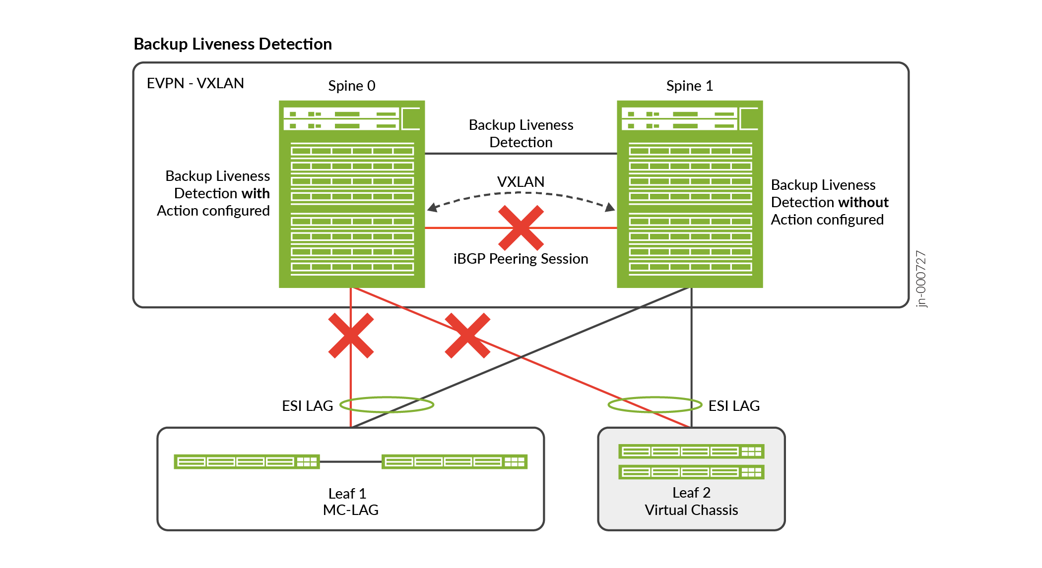
The node liveness detection uses BFD configured between the EVPN peers with one side configured to take action based on the BFD and BGP status. This action ensures traffic forwarding continues through the network. The BFD liveness session can run over standard interfaces or over the management interfaces between the EVPN BGP peer devices. Node liveness needs to be detected even when the link between the Spines is down. So, node liveness detection should run over a separate network.
Junos OS Evolved platforms do not support BFD over management ports.
Benefits of Backup Liveness Detection
-
Can keep the leaf facing links up on one of the devices in a dual-homed environment during a core isolation event.
-
Ensures internal traffic continues even with a BGP failure on the Spine devices.
Behavior
The node liveness feature behaves as follows. When the BGP session is up, both peers keep
their leaf facing ESI-LAG interfaces up. When the BGP session is down but the BFD session is
up. The Spine with the action configured brings its leaf facing ESI-LAG
interfaces down. The Spine which has no action configured will keep its
ESI-LAG facing the leaf devices up. When the BGP session and the BFD session tracking the
node liveness are down, it indicates one of the Spine devices has gone down. Then the Spine
with the action configured will keep its leaf facing ESI-LAG interfaces up
if it is active. When the BFD session comes back up, the Spine with action
configured will again bring its leaf facing ESI-LAG interfaces down.
Table 1 summarizes the state on each of the Spine devices in the different scenarios. The
actions configured will be either laser-off or
trigger-node-isolation. With laser-off as the action the
leaf facing ESI-LAG would receive a laser-off signal on core-isolation. If the action
configured is trigger-node-isolation the l2 process will place the leaf
facing ESI-LAG links in link-down state.
|
BGP State |
Node Liveness BFD State |
On Spine with |
On Spine with |
Comments |
|---|---|---|---|---|
|
Up -> Down |
Down |
ESI-LAG remains up |
ESI-LAG remains up |
For example, on Spine 0 both BGP and liveness are down Which means that Spine 1 is unavailable. Keep ESI LAG UP regardless of action configuration |
|
Up -> Down |
Up |
Bring ESI-LAG down |
ESI-LAG remains up |
BGP state is down. But BFD is up. This indicates a split-brain scenario. Only one ESI LAG must be up. So shut down the ESI LAG on the device with the action configured. |
|
Down -> Up |
Down |
If ESI LAG is down, bring it up. |
ESI-LAG remains up |
BGP status takes precedence |
|
Down -> Up |
Up |
If ESI LAG is down, bring it up. |
ESI-LAG remains up |
BGP status takes precedence |
Limitations
-
Junos OS Evolved platforms do not support BFD over management ports, due to a Junos OS Evolved limitation that prevents sending protocol packets over a management port.
-
EVPN node liveness detection does not support Multihop BFD. Configure node liveness detection over directly connected interfaces.
-
Configuring
no-core-isolationoverridesnode-detectionconfigurations.
Configure EVPN Backup Liveness Detection
Configure the following elements to enable the backup liveness detection feature for an EVPN peer:
1. Configure node-detection on both EVPN
peers with the action configured only on one peer.
-
Peer 1 with
actionconfigured[edit] set protocols evpn node-detection next-hop interface; set protocols evpn node-detection action (laser-off | trigger-node-isolation); set protocols evpn node-detection bfd-liveness-detection minimum-interval interval; set protocols evpn node-detection bfd-liveness-detection multiplier number; set protocols evpn node-detection bfd-liveness-detection neighbor ip address;
-
Peer 2 without
actionconfigured [edit] set protocols evpn node-detection next-hop interface; set protocols evpn node-detection bfd-liveness-detection minimum-interval interval; set protocols evpn node-detection bfd-liveness-detection multiplier number; set protocols evpn node-detection bfd-liveness-detection neighbor ip address;
2. If the laser-off statement is used, then you must configure asychronous-notification for the members of the ESI LAG.
[edit]
set interfaces interface gigether-options asynchronous-notification;
3. If the trigger-node-isolation statement is used, then you must configure network-isolation with the link-down action to bring the necessary interfaces down on core isolation.
[edit]
set protocols network-isolation group name detection hold-time up milliseconds;
set protocols network-isolation group name detection service-tracking core-isolation;
set protocols network-isolation group name service-tracking-action (link-down | lacp-oos);
Verifying Status
You can view the BFD from the peer devices by using the show bfd session command.
> show bfd session
                                                 Detect   Transmit
Address                  State     Interface      Time     Interval  Multiplier
1.0.0.2                  Up        ge-0/0/3.0     0.300     0.100        3

1 sessions, 1 clients
Cumulative transmit rate 10.0 pps, cumulative receive rate 10.0 pps
When the action set is laser-off, you can examine the
system log messages for state information.
> show log messages | match isolat
Sep  6 17:48:55  Core1 18956[EVPN_CORE_ISOLATED]:
Sep  6 17:48:55  Core1 18956[EVPN_vmm _ISOLATED]:
Sep  6 17:48:59  Core1 18956[EVPN_CORE_ISOLATED]:
Sep  6 17:48:59  Core1 18956[EVPN_CORE_ISOLATED]:
Sep  6 17:49:55  Core1 18956[EVPN_CORE_ISOLATION_CLEARED]:
Sep  6 17:50:05  Core1 18956[EVPN_CORE_ISOLATION_CLEARED]:
Sep  6 17:50:05  Core1 18956[EVPN_CORE_ISOLATION_CLEARED]: