Example: EVPN-MPLS Interworking With Junos Fusion Enterprise
This example shows how to use Ethernet VPN (EVPN) to extend a Junos Fusion Enterprise over an MPLS network to a geographically distributed campus or enterprise network.
EVPN-MPLS interworking is supported with a Junos Fusion Enterprise, which is based on a multichassis link aggregation group (MC-LAG) infrastructure to provide redundancy for the EX9200 switches that function as aggregation devices.
The aggregation devices in the Junos Fusion Enterprise are connected to a provider edge (PE) device in an MPLS network. The PE device can be either an MX Series router or an EX9200 switch.
This example shows how to configure the aggregation devices in the Junos Fusion Enterprise and the PE device in the MPLS network to interwork with each other.
Requirements
This example uses the following hardware and software components:
Three EX9200 switches:
PE1 and PE2, which both function as aggregation devices in the Junos Fusion Enterprise and EVPN BGP peers in the EVPN-MPLS overlay network.
PE3, which functions as an EVPN BGP peer in the EVPN-MPLS overlay network.
The EX9200 switches are running Junos OS Release 17.4R1 or later software.
Although the Junos Fusion Enterprise includes three satellite devices, this example focuses on the configuration of the PE1, PE2, and PE3. For more information about configuring satellite devices, see Configuring or Expanding a Junos Fusion Enterprise.
Overview and Topology
Figure 1 shows a Junos Fusion Enterprise with dual aggregation devices PE1 and PE2. The aggregation devices are connected using an interchassis link (ICL) and communicate with each other using the Inter-Chassis Control Protocol (ICCP).
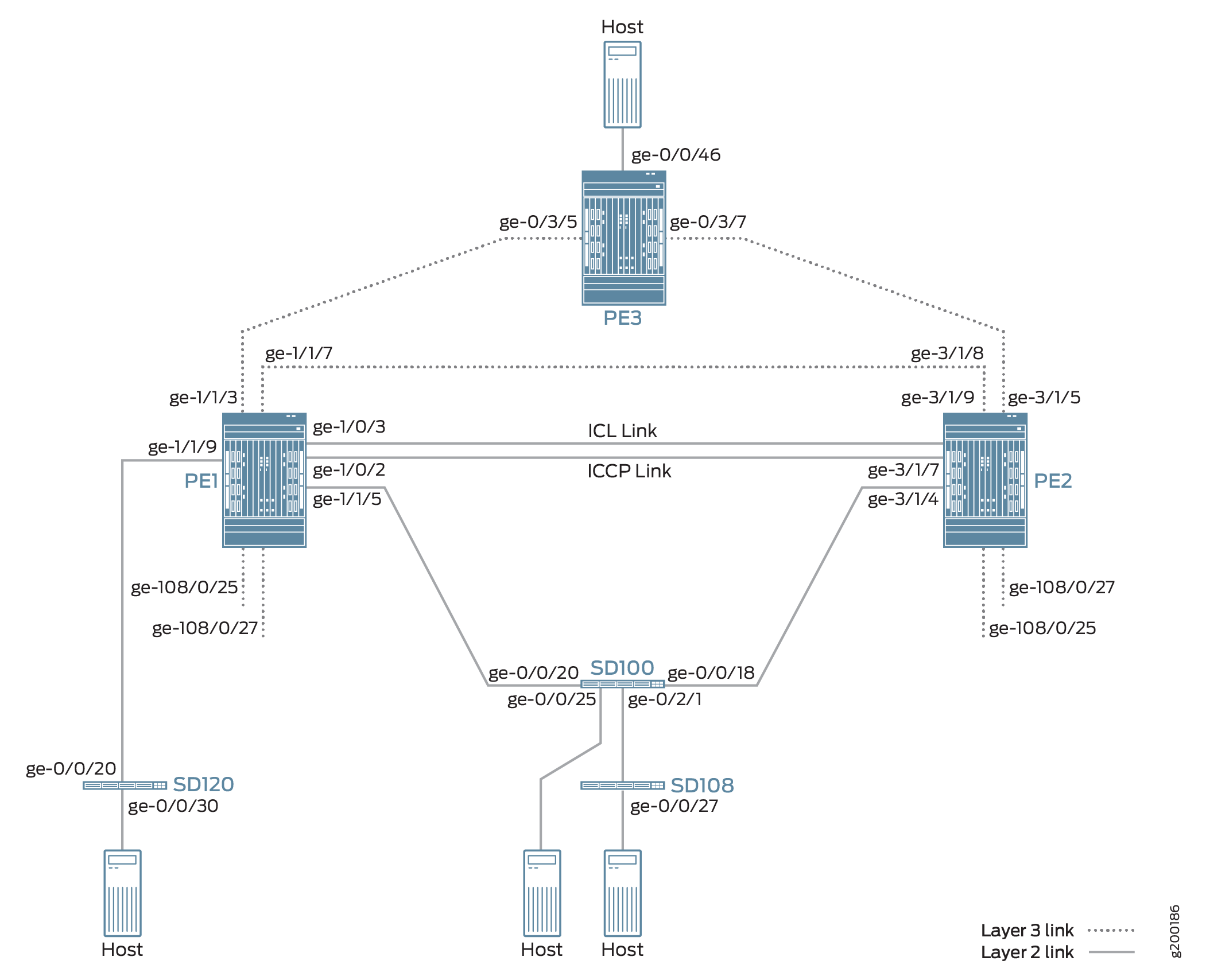
The Junos Fusion Enterprise also includes three satellite devices. Satellite device SD120 is a standalone satellite device that has a single-homed connection to PE1. Satellite devices SD100 and SD108 are included in a cluster named Cluster_100_108. SD100 is the only cluster member with a connection to an aggregation device, in this case, multhomed connections to PE1 and PE2.
The topology in Figure 1 also includes PE3, which is positioned at the edge of an MPLS network. PE3 functions as the gateway between the Junos Fusion Enterprise network and a geographically distributed campus or enterprise network. PE1, PE2, and PE3 run EVPN, which enables hosts in the Junos Fusion Enterprise network to communicate with hosts in the campus or enterprise network by way of the intervening MPLS network.
From the perspective of the EVPN-MPLS interworking feature, PE3 functions solely as an EVPN BGP peer, and PE1 and PE2 in the Junos Fusion Enterprise have dual roles:
Aggregation devices in the Junos Fusion Enterprise.
EVPN BGP peers in the EVPN-MPLS network.
Because of the dual roles, PE1 and PE2 are configured with Junos Fusion Enterprise, EVPN, BGP, and MPLS attributes.
Table 1 outlines key Junos Fusion Enterprise and EVPN (BGP and MPLS) attributes configured on PE1, PE2, and PE3.
Key Attributes |
PE1 |
PE2 |
PE3 |
|---|---|---|---|
Junos Fusion Enterprise Attributes |
|||
Interfaces |
ICL: ge-1/0/3 ICCP: ge-1/0/2 |
ICL: ge-3/1/9 ICCP: ge-3/1/7 |
Not applicable |
EVPN-MPLS |
|||
Interfaces |
Connection to PE3: ge-1/1/3 Connection to PE2: ge-1/1/7 |
Connection to PE3: ge-3/1/5 Connection to PE1: ge-3/1/8 |
Connection to PE1: ge-0/3/5 Connection to PE2: ge-0/3/7 |
IP addresses |
BGP peer address: 10.25.0.1 |
BGP peer address: 10.25.0.2 |
BGP peer address: 10.25.0.3 |
Autonomous system |
100 |
100 |
100 |
Virtual switch routing instances |
evpn1 |
evpn1 |
evpn1 |
Note the following about the EVPN-MPLS interworking feature and its configuration:
You must configure Ethernet segment identifiers (ESIs) on the dual-homed extended ports in the Junos Fusion Enterprise. The ESIs enable EVPN to identify the dual-homed extended ports.
The only type of routing instance that is supported is the virtual switch instance (
set routing-instances name instance-type virtual-switch).Only one virtual switch instance is supported with Junos Fusion Enterprise.
On the aggregation devices in the Junos Fusion Enterprise, you must include the
bgp-peerconfiguration statement in the[edit routing-instances name protocols evpn mclag]hierarchy level. This configuration statement enables the interworking of EVPN-MPLS with Junos Fusion Enterprise on the aggregation devices.Address Resolution Protocol (ARP) suppression is not supported.
Aggregation Device (PE1 and PE2) Configuration
To configure aggregation devices PE1 and PE2, perform these tasks.
This section focuses on enabling EVPN-MPLS on PE1 and PE2. As a result, the Junos Fusion Enterprise configuration on PE1 and PE2 is performed without the use of the configuration synchronization feature. For information about configuration synchronization, see Understanding Configuration Synchronization.
- CLI Quick Configuration
- PE1: Configuring Junos Fusion Enterprise
- PE1: Configuring EVPN-MPLS
- PE2: Configuring Junos Fusion Enterprise
- PE2: Configuring EVPN-MPLS
CLI Quick Configuration
PE1: Junos Fusion Enterprise Configuration
set interfaces ge-1/1/9 cascade-port
set interfaces ge-1/1/5 cascade-port
set chassis satellite-management fpc 120 cascade-ports ge-1/1/9
set chassis satellite-management cluster Cluster_100_108 cluster-id 2
set chassis satellite-management cluster Cluster_100_108 cascade-ports ge-1/1/5
set chassis satellite-management cluster Cluster_100_108 fpc 100 alias SD100
set chassis satellite-management cluster Cluster_100_108 fpc 100 system-id 88:e0:f3:1f:3d:50
set chassis satellite-management cluster Cluster_100_108 fpc 108 alias SD108
set chassis satellite-management cluster Cluster_100_108 fpc 108 system-id 88:e0:f3:1f:c8:d1
set chassis satellite-management cluster Cluster_100_108 fpc 100 member-id 1
set chassis satellite-management cluster Cluster_100_108 fpc 108 member-id 8
set chassis satellite-management upgrade-groups upgrade_120 satellite 120
set chassis satellite-management upgrade-groups upgrade_100 satellite 100
set chassis satellite-management redundancy-groups rg1 redundancy-group-id 2
set chassis satellite-management redundancy-groups chassis-id 1
set chassis satellite-management redundancy-groups rg1 peer-chassis-id 2 inter-chassis-link ge-1/0/3
set chassis satellite-management redundancy-groups rg1 cluster Cluster_100_108
set interfaces ge-1/0/2 description iccp-link
set interfaces ge-1/0/2 unit 0 family inet address 10.20.20.1/24
set interfaces ge-1/0/3 description icl-link
set interfaces ge-1/0/3 unit 0 family ethernet-switching interface-mode trunk
set interfaces ge-1/0/3 unit 0 family ethernet-switching vlan members 100
set switch-options service-id 1
PE1: EVPN-MPLS Configuration
set interfaces lo0 unit 0 family inet address 10.25.0.1/32
set interfaces ge-1/1/3 unit 0 family inet address 10.0.1.1/30
set interfaces ge-1/1/3 unit 0 family mpls
set interfaces ge-1/1/7 unit 0 family inet address 10.0.3.1/30
set interfaces ge-1/1/7 unit 0 family mpls
set interfaces ge-108/0/25 unit 0 esi 00:01:02:03:04:00:01:02:04:26
set interfaces ge-108/0/25 unit 0 esi all-active
set interfaces ge-108/0/25 unit 0 family ethernet-switching vlan members v100
set interfaces ge-108/0/27 unit 0 esi 00:01:02:03:04:00:01:02:04:28
set interfaces ge-108/0/27 unit 0 esi all-active
set interfaces ge-108/0/27 unit 0 family ethernet-switching vlan members v100
set routing-options router-id 10.25.0.1
set routing-options autonomous-system 100
set protocols mpls interface lo0.0
set protocols mpls interface ge-1/1/3.0
set protocols mpls interface ge-1/1/7.0
set protocols bgp local-address 10.25.0.1
set protocols bgp peer-as 100
set protocols bgp local-as 100
set protocols bgp group evpn-mes type internal
set protocols bgp group evpn-mes family evpn signaling
set protocols bgp group evpn-mes peer-as 100
set protocols bgp group evpn-mes neighbor 10.25.0.2
set protocols bgp group evpn-mes neighbor 10.25.0.3
set protocols ospf traffic-engineering
set protocols ospf area 0.0.0.0 interface ge-1/1/3.0
set protocols ospf area 0.0.0.0 interface lo0.0
set protocols ospf area 0.0.0.0 interface fxp0.0 disable
set protocols ospf area 0.0.0.0 interface ge-1/1/7.0
set protocols ldp interface lo0.0
set protocols ldp interface ge-1/1/3.0
set protocols ldp interface ge-1/1/7.0
set routing-instances evpn1 instance-type virtual-switch
set routing-instances evpn1 interface ge-108/0/25.0
set routing-instances evpn1 interface ge-108/0/27.0
set routing-instances evpn1 interface ge-1/0/3.0
set routing-instances evpn1 route-distinguisher 10.25.0.1:1
set routing-instances evpn1 vrf-target target:100:1
set routing-instances evpn1 protocols evpn label-allocation per-instance
set routing-instances evpn1 protocols evpn extended-vlan-list 100
set routing-instances evpn1 protocols evpn mclag bgp-peer 10.25.0.2
set routing-instances evpn1 switch-options service-id 2
set routing-instances evpn1 vlans v100 vlan-id 100
PE2: Junos Fusion Enterprise Configuration
set interfaces ge-3/1/4 cascade-port
set chassis satellite-management cluster Cluster_100_108 cluster-id 2
set chassis satellite-management cluster Cluster_100_108 cascade-ports ge-3/1/4
set chassis satellite-management cluster Cluster_100_108 fpc 100 alias SD100
set chassis satellite-management cluster Cluster_100_108 fpc 100 system-id 88:e0:f3:1f:3d:50
set chassis satellite-management cluster Cluster_100_108 fpc 108 alias SD108
set chassis satellite-management cluster Cluster_100_108 fpc 108 system-id 88:e0:f3:1f:c8:d1
set chassis satellite-management cluster Cluster_100_108 fpc 100 member-id 1
set chassis satellite-management cluster Cluster_100_108 fpc 108 member-id 8
set chassis satellite-management upgrade-groups upgrade_100 satellite 100
set chassis satellite-management redundancy-groups rg1 redundancy-group-id 2
set chassis satellite-management redundancy-groups chassis-id 2
set chassis satellite-management redundancy-groups rg1 peer-chassis-id 1 inter-chassis-link ge-3/1/9
set chassis satellite-management redundancy-groups rg1 cluster Cluster_100_108
set interfaces ge-3/1/7 description iccp-link
set interfaces ge-3/1/7 unit 0 family inet address 10.20.20.2/24
set interfaces ge-3/1/9 description icl-link
set interfaces ge-3/1/9 unit 0 family ethernet-switching interface-mode trunk
set interfaces ge-3/1/9 unit 0 family ethernet-switching vlan members 100
set switch-options service-id 1
PE2: EVPN-MPLS Configuration
set interfaces lo0 unit 0 family inet address 10.25.0.2/32
set interfaces ge-3/1/5 unit 0 family inet address 10.0.4.2/30
set interfaces ge-3/1/5 unit 0 family mpls
set interfaces ge-3/1/8 unit 0 family inet address 10.0.3.2/30
set interfaces ge-3/1/8 unit 0 family mpls
set interfaces irb unit 0 family inet address 10.5.5.1/24 virtual-gateway-address 10.5.5.5
set interfaces ge-108/0/25 unit 0 esi 00:01:02:03:04:00:01:02:04:26
set interfaces ge-108/0/25 unit 0 esi all-active
set interfaces ge-108/0/25 unit 0 family ethernet-switching vlan members v100
set interfaces ge-108/0/27 unit 0 esi 00:01:02:03:04:00:01:02:04:28
set interfaces ge-108/0/27 unit 0 esi all-active
set interfaces ge-108/0/27 unit 0 family ethernet-switching vlan members v100
set routing-options router-id 10.25.0.2
set routing-options autonomous-system 100
set protocols mpls interface lo0.0
set protocols mpls interface ge-3/1/5.0
set protocols mpls interface ge-3/1/8.0
set protocols bgp local-address 10.25.0.2
set protocols bgp peer-as 100
set protocols bgp local-as 100
set protocols bgp group evpn-mes type internal
set protocols bgp group evpn-mes family evpn signaling
set protocols bgp group evpn-mes peer-as 100
set protocols bgp group evpn-mes neighbor 10.25.0.1
set protocols bgp group evpn-mes neighbor 10.25.0.3
set protocols ospf traffic-engineering
set protocols ospf area 0.0.0.0 interface ge-3/1/5.0
set protocols ospf area 0.0.0.0 interface lo0.0
set protocols ospf area 0.0.0.0 interface fxp0.0 disable
set protocols ospf area 0.0.0.0 interface ge-3/1/8.0
set protocols ldp interface lo0.0
set protocols ldp interface ge-3/1/5.0
set protocols ldp interface ge-3/1/8.0
set routing-instances evpn1 instance-type virtual-switch
set routing-instances evpn1 interface ge-108/0/25.0
set routing-instances evpn1 interface ge-108/0/27.0
set routing-instances evpn1 interface ge-3/1/9.0
set routing-instances evpn1 route-distinguisher 10.25.0.2:1
set routing-instances evpn1 vrf-target target:100:1
set routing-instances evpn1 protocols evpn label-allocation per-instance
set routing-instances evpn1 protocols evpn extended-vlan-list 100
set routing-instances evpn1 protocols evpn mclag bgp-peer 10.25.0.1
set routing-instances evpn1 switch-options service-id 2
set routing-instances evpn1 vlans v100 vlan-id 100
set routing-instances evpn1 vlans v100 l3-interface irb.0
PE1: Configuring Junos Fusion Enterprise
Step-by-Step Procedure
Configure the cascade ports.
[edit]
user@switch# set interfaces ge-1/1/9 cascade-port
user@switch# set interfaces ge-1/1/5 cascade-port
Configure the FPC slot ID for standalone satellite device SD120 and map it to a cascade port.
[edit]
user@switch# set chassis satellite-management fpc 120 cascade-ports ge-1/1/9
Create a satellite device cluster, and assign a name and a cluster ID to it.
[edit]
user@switch# set chassis satellite-management cluster Cluster_100_108 cluster-id 2
Define the cascade ports associated with the satellite device cluster.
[edit]
user@switch# set chassis satellite-management cluster Cluster_100_108 cascade-ports ge-1/1/5
user@switch# set chassis satellite-management cluster Cluster_100_108 cascade-ports ge-1/1/9
Configure the FPC slot ID number, and map it to the MAC address of satellite devices SD100 and SD108, respectively.
[edit]
user@switch# set chassis satellite-management cluster Cluster_100_108 fpc 100 alias SD100
user@switch# set chassis satellite-management cluster Cluster_100_108 fpc 100 system-id 88:e0:f3:1f:3d:50
user@switch# set chassis satellite-management cluster Cluster_100_108 fpc 108 alias SD108
user@switch# set chassis satellite-management cluster Cluster_100_108 fpc 108 system-id 88:e0:f3:1f:c8:d1
Assign a member ID to each satellite device in the satellite device cluster.
[edit]
user@switch# set chassis satellite-management cluster Cluster_100_108 fpc 100 member-id 1
user@switch# set chassis satellite-management cluster Cluster_100_108 fpc 108 member-id 8
Create two satellite software upgrade groups—one that includes satellite device SD120 and another that includes satellite device SD100.
[edit]
user@switch# set chassis satellite-management upgrade-groups upgrade_120 satellite 120
user@switch# set chassis satellite-management upgrade-groups upgrade_100 satellite 100
Create and configure a redundancy group, which includes the aggregation devices and satellite devices in Cluster_100_108.
[edit]
user@switch# set chassis satellite-management redundancy-groups rg1 redundancy-group-id 2
user@switch# set chassis satellite-management redundancy-groups chassis-id 1
user@switch# set chassis satellite-management redundancy-groups rg1 peer-chassis-id 2 inter-chassis-link ge-1/0/3
user@switch# set chassis satellite-management redundancy-groups rg1 cluster Cluster_100_108
Configure the ICL and ICCP links.
[edit]
user@switch# set interfaces ge-1/0/2 description iccp-link
user@switch# set interfaces ge-1/0/2 unit 0 family inet address 10.20.20.1/24
user@switch# set interfaces ge-1/0/3 description icl-link
user@switch# set interfaces ge-1/0/3 unit 0 family ethernet-switching interface-mode trunk
user@switch# set interfaces ge-1/0/3 unit 0 family ethernet-switching vlan members 100
user@switch# set switch-options service-id 1
Note:While this step shows the configuration of interface ge-1/0/2, which is designated as the ICCP interface, it does not show how to configure the ICCP attributes on interface ge-1/0/2. By default, ICCP is automatically provisioned in a Junos Fusion Enterprise using dual aggregation devices. For more information about the automatic provisioning of ICCP, see Configuring or Expanding a Junos Fusion Enterprise.
PE1: Configuring EVPN-MPLS
Step-by-Step Procedure
Configure the loopback interface and the interfaces connected to the other PE devices.
[edit]
user@switch# set interfaces lo0 unit 0 family inet address 10.25.0.1/32
user@switch# set interfaces ge-1/1/3 unit 0 family inet address 10.0.1.1/30
user@switch# set interfaces ge-1/1/3 unit 0 family mpls
user@switch# set interfaces ge-1/1/7 unit 0 family inet address 10.0.3.1/30
user@switch# set interfaces ge-1/1/7 unit 0 family mpls
Configure the extended ports with EVPN multihoming in active-active mode, an ESI, and map the ports to VLAN v100..
[edit]
user@switch# set interfaces ge-108/0/25 unit 0 esi 00:01:02:03:04:00:01:02:04:26
user@switch# set interfaces ge-108/0/25 unit 0 esi all-active
user@switch# set interfaces ge-108/0/25 unit 0 family ethernet-switching vlan members v100
user@switch# set interfaces ge-108/0/27 unit 0 esi 00:01:02:03:04:00:01:02:04:28
user@switch# set interfaces ge-108/0/27 unit 0 esi all-active
user@switch# set interfaces ge-108/0/27 unit 0 family ethernet-switching vlan members v100
Assign a router ID and the autonomous system in which PE1, PE2, and PE3 reside.
[edit]
user@switch# set routing-options router-id 10.25.0.1
user@switch# set routing-options autonomous-system 100
Enable MPLS on the loopback interface and interfaces ge-1/1/3.0 and ge-1/1/7.0.
[edit]
user@switch# set protocols mpls interface lo0.0
user@switch# set protocols mpls interface ge-1/1/3.0
user@switch# set protocols mpls interface ge-1/1/7.0
Configure an IBGP overlay that includes PE1, PE2, and PE3.
[edit]
user@switch# set protocols bgp local-address 10.25.0.1
user@switch# set protocols bgp peer-as 100
user@switch# set protocols bgp local-as 100
user@switch# set protocols bgp group evpn-mes type internal
user@switch# set protocols bgp group evpn-mes family evpn signaling
user@switch# set protocols bgp group evpn-mes peer-as 100
user@switch# set protocols bgp group evpn-mes neighbor 10.25.0.2
user@switch# set protocols bgp group evpn-mes neighbor 10.25.0.3
Configure OSPF as the internal routing protocol for EVPN by specifying an area ID and interfaces on which EVPN-MPLS is enabled.
[edit]
user@switch# set protocols ospf traffic-engineering
user@switch# set protocols ospf area 0.0.0.0 interface ge-1/1/3.0
user@switch# set protocols ospf area 0.0.0.0 interface lo0.0
user@switch# set protocols ospf area 0.0.0.0 interface fxp0.0 disable
user@switch# set protocols ospf area 0.0.0.0 interface ge-1/1/7.0
Configure the Label Distribution Protocol (LDP) on the loopback interface and the interfaces on which EVPN-MPLS is enabled.
[edit]
user@switch# set protocols ldp interface lo0.0
user@switch# set protocols ldp interface ge-1/1/3.0
user@switch# set protocols ldp interface ge-1/1/7.0
Configure a virtual switch routing instance for VLAN v100, and include the interfaces and other entities associated with the VLAN.
[edit]
user@switch# set routing-instances evpn1 instance-type virtual-switch
user@switch# set routing-instances evpn1 interface ge-108/0/25.0
user@switch# set routing-instances evpn1 interface ge-108/0/27.0
user@switch# set routing-instances evpn1 interface ge-1/0/3.0
user@switch# set routing-instances evpn1 route-distinguisher 10.25.0.1:1
user@switch# set routing-instances evpn1 vrf-target target:100:1
user@switch# set routing-instances evpn1 protocols evpn label-allocation per-instance
user@switch# set routing-instances evpn1 protocols evpn extended-vlan-list 100
user@switch# set routing-instances evpn1 protocols evpn mclag bgp-peer 10.25.0.2
user@switch# set routing-instances evpn1 switch-options service-id 2
user@switch# set routing-instances evpn1 vlans v100 vlan-id 100
PE2: Configuring Junos Fusion Enterprise
Step-by-Step Procedure
Configure the cascade port.
[edit]
user@switch# set interfaces ge-3/1/4 cascade-port
Create a satellite device cluster, and assign a name and a cluster ID to it.
[edit]
user@switch# set chassis satellite-management cluster Cluster_100_108 cluster-id 2
Define the cascade port associated with the satellite device cluster.
[edit]
user@switch# set chassis satellite-management cluster Cluster_100_108 cascade-ports ge-3/1/4
Configure the FPC slot ID number, and map it to the MAC address of satellite devices SD100 and SD108, respectively.
[edit]
user@switch# set chassis satellite-management cluster Cluster_100_108 fpc 100 alias SD100
user@switch# set chassis satellite-management cluster Cluster_100_108 fpc 100 system-id 88:e0:f3:1f:3d:50
user@switch# set chassis satellite-management cluster Cluster_100_108 fpc 108 alias SD108
user@switch# set chassis satellite-management cluster Cluster_100_108 fpc 108 system-id 88:e0:f3:1f:c8:d1
Assign a member ID to each satellite device in the satellite device cluster.
[edit]
user@switch# set chassis satellite-management cluster Cluster_100_108 fpc 100 member-id 1
user@switch# set chassis satellite-management cluster Cluster_100_108 fpc 108 member-id 8
Create a satellite software upgrade group that includes satellite device SD100.
[edit]
user@switch# set chassis satellite-management upgrade-groups upgrade_100 satellite 100
Create and configure a redundancy group, which includes the aggregation devices and satellite devices in Cluster_100_108.
[edit]
user@switch# set chassis satellite-management redundancy-groups rg1 redundancy-group-id 2
user@switch# set chassis satellite-management redundancy-groups chassis-id 2
user@switch# set chassis satellite-management redundancy-groups rg1 peer-chassis-id 1inter-chassis-link ge-3/1/9
user@switch# set chassis satellite-management redundancy-groups rg1 cluster Cluster_100_108
Configure the ICL and ICCP links.
[edit]
user@switch# set interfaces ge-3/1/7 description iccp-link
user@switch# set interfaces ge-3/1/7 unit 0 family inet address 10.20.20.2/24
user@switch# set interfaces ge-3/1/9 description icl-link
user@switch# set interfaces ge-3/1/9 unit 0 family ethernet-switching interface-mode trunk
user@switch# set interfaces ge-3/1/9 unit 0 family ethernet-switching vlan members 100
user@switch# set switch-options service-id 1
Note:While this step shows the configuration of interface ge-3/1/7, which is designated as the ICCP interface, it does not show how to configure the ICCP attributes on interface ge-3/1/7. By default, ICCP is automatically provisioned in a Junos Fusion Enterprise using dual aggregation devices. For more information about the automatic provisioning of ICCP, see Configuring or Expanding a Junos Fusion Enterprise.
PE2: Configuring EVPN-MPLS
Step-by-Step Procedure
Configure the loopback interface, the interfaces connected to the other PE devices, and an IRB interface that is also configured as a default Layer 3 gateway.
[edit]
user@switch# set interfaces lo0 unit 0 family inet address 10.25.0.2/32
user@switch# set interfaces ge-3/1/5 unit 0 family inet address 10.0.4.2/30
user@switch# set interfaces ge-3/1/5 unit 0 family mpls
user@switch# set interfaces ge-3/1/8 unit 0 family inet address 10.0.3.2/30
user@switch# set interfaces ge-3/1/8 unit 0 family mpls
user@switch# set interfaces irb unit 0 family inet address 10.5.5.1/24 virtual-gateway-address 10.5.5.5
Configure the extended ports with EVPN multihoming in active-active mode, an ESI, and map the ports to VLAN v100..
[edit]
user@switch# set interfaces ge-108/0/25 unit 0 esi 00:01:02:03:04:00:01:02:04:26
user@switch# set interfaces ge-108/0/25 unit 0 esi all-active
user@switch# set interfaces ge-108/0/25 unit 0 family ethernet-switching vlan members v100
user@switch# set interfaces ge-108/0/27 unit 0 esi 00:01:02:03:04:00:01:02:04:28
user@switch# set interfaces ge-108/0/27 unit 0 esi all-active
user@switch# set interfaces ge-108/0/27 unit 0 family ethernet-switching vlan members v100
Assign a router ID and the autonomous system in which PE1, PE2, and PE3 reside.
[edit]
user@switch# set routing-options router-id 10.25.0.2
user@switch# set routing-options autonomous-system 100
Enable MPLS on the loopback interface and interfaces ge-3/1/5.0 and ge-3/1/8.0.
[edit]
user@switch# set protocols mpls interface lo0.0
user@switch# set protocols mpls interface ge-3/1/5.0
user@switch# set protocols mpls interface ge-3/1/8.0
Configure an IBGP overlay that includes PE1, PE2, and PE3.
[edit]
user@switch# set protocols bgp local-address 10.25.0.2
user@switch# set protocols bgp peer-as 100
user@switch# set protocols bgp local-as 100
user@switch# set protocols bgp group evpn-mes type internal
user@switch# set protocols bgp group evpn-mes family evpn signaling
user@switch# set protocols bgp group evpn-mes peer-as 100
user@switch# set protocols bgp group evpn-mes neighbor 10.25.0.1
user@switch# set protocols bgp group evpn-mes neighbor 10.25.0.3
Configure OSPF as the internal routing protocol for EVPN by specifying an area ID and interfaces on which EVPN-MPLS is enabled.
[edit]
user@switch# set protocols ospf traffic-engineering
user@switch# set protocols ospf area 0.0.0.0 interface ge-3/1/5.0
user@switch# set protocols ospf area 0.0.0.0 interface lo0.0
user@switch# set protocols ospf area 0.0.0.0 interface fxp0.0 disable
user@switch# set protocols ospf area 0.0.0.0 interface ge-3/1/8.0
Configure the LDP on the loopback interface and the interfaces on which EVPN-MPLS is enabled.
[edit]
user@switch# set protocols ldp interface lo0.0
user@switch# set protocols ldp interface ge-3/1/5.0
user@switch# set protocols ldp interface ge-3/1/8.0
Configure a virtual switch routing instance for VLAN v100, and include the interfaces and other entities associated with the VLAN.
[edit]
user@switch# set routing-instances evpn1 instance-type virtual-switch
user@switch# set routing-instances evpn1 interface ge-108/0/25.0
user@switch# set routing-instances evpn1 interface ge-108/0/27.0
user@switch# set routing-instances evpn1 interface ge-3/1/9.0
user@switch# set routing-instances evpn1 route-distinguisher 10.25.0.2:1
user@switch# set routing-instances evpn1 vrf-target target:100:1
user@switch# set routing-instances evpn1 protocols evpn label-allocation per-instance
user@switch# set routing-instances evpn1 protocols evpn extended-vlan-list 100
user@switch# set routing-instances evpn1 protocols evpn mclag bgp-peer 10.25.0.1
user@switch# set routing-instances evpn1 switch-options service-id 2
user@switch# set routing-instances evpn1 vlans v100 vlan-id 100
user@switch# set routing-instances evpn1 vlans v100 l3-interface irb.0
PE3 Configuration
CLI Quick Configuration
PE3: EVPN-MPLS Configuration
set interfaces lo0 unit 0 family inet address 10.25.0.3/32
set interfaces ge-0/3/5 unit 0 family inet address 10.0.1.2/30
set interfaces ge-0/3/5 unit 0 family mpls
set interfaces ge-0/3/7 unit 0 family inet address 10.0.4.1/30
set interfaces ge-0/3/7 unit 0 family mpls
set interfaces ge-0/0/46 unit 0 esi 00:01:02:03:04:00:01:02:04:12
set interfaces ge-0/0/46 unit 0 esi all-active
set interfaces ge-0/0/46 unit 0 family ethernet-switching vlan members 100
set routing-options router-id 10.25.0.3
set routing-options autonomous-system 100
set routing-options forwarding-table export evpn-pplb
set policy-options policy-statement evpn-pplb from protocol evpn
set policy-options policy-statement evpn-pplb then load-balance per-packet
set protocols mpls interface lo0.0
set protocols mpls interface ge-0/3/5.0
set protocols mpls interface ge-0/3/7.0
set protocols bgp local-address 10.25.0.3
set protocols bgp peer-as 100
set protocols bgp local-as 100
set protocols bgp group evpn-mes type internal
set protocols bgp group evpn-mes family evpn signaling
set protocols bgp group evpn-mes peer-as 100
set protocols bgp group evpn-mes neighbor 10.25.0.2
set protocols bgp group evpn-mes neighbor 10.25.0.1
set protocols ospf traffic-engineering
set protocols ospf area 0.0.0.0 interface ge-0/3/5.0
set protocols ospf area 0.0.0.0 interface lo0.0
set protocols ospf area 0.0.0.0 interface fxp0.0 disable
set protocols ospf area 0.0.0.0 interface ge-0/3/7.0
set protocols ldp interface lo0.0
set protocols ldp interface ge-0/3/5.0
set protocols ldp interface ge-0/3/7.0
set routing-instances evpn1 instance-type virtual-switch
set routing-instances evpn1 interface ge-0/0/46.0
set routing-instances evpn1 route-distinguisher 10.25.0.3:1
set routing-instances evpn1 vrf-target target:100:1
set routing-instances evpn1 protocols evpn label-allocation per-instance
set routing-instances evpn1 protocols evpn extended-vlan-list 100
set routing-instances evpn1 switch-options service-id 2
set routing-instances evpn1 vlans v100 vlan-id 100
PE3: Configuring EVPN-MPLS
Step-by-Step Procedure
Configure the interfaces on EVPN-MPLS interworking occurs.
[edit]
user@switch# set interfaces lo0 unit 0 family inet address 10.25.0.3/32
user@switch# set interfaces ge-0/3/5 unit 0 family inet address 10.0.1.2/30
user@switch# set interfaces ge-0/3/5 unit 0 family mpls
user@switch# set interfaces ge-0/3/7 unit 0 family inet address 10.0.4.1/30
user@switch# set interfaces ge-0/3/7 unit 0 family mpls
Configure interface ge-0/0/46 with EVPN multihoming in active-active mode, an ESI, and map the ports to VLAN v100..
[edit]
user@switch# set interfaces ge-0/0/46 unit 0 esi 00:01:02:03:04:00:01:02:04:12
user@switch# set interfaces ge-0/0/46 unit 0 esi all-active
user@switch# set interfaces ge-0/0/46 unit 0 family ethernet-switching vlan members 100
Assign a router ID and the autonomous system in which the PE1, PE2, and PE3 reside.
[edit]
user@switch# set routing-options router-id 10.25.0.2
user@switch# set routing-options autonomous-system 100
Enable per-packet load-balancing for EVPN routes when EVPN multihoming active-active mode is used.
[edit]
user@switch# set routing-options forwarding-table export evpn-pplb
user@switch# set policy-options policy-statement evpn-pplb from protocol evpn
user@switch# set policy-options policy-statement evpn-pplb then load-balance per-packet
Enable MPLS on the loopback interface and interfaces ge-0/3/5.0 and ge-0/3/7.0.
[edit]
user@switch# set protocols mpls interface lo0.0
user@switch# set protocols mpls interface ge-0/3/5.0
user@switch# set protocols mpls interface ge-0/3/7.0
Configure an IBGP overlay that includes PE1, PE2, and PE3.
[edit]
user@switch# set protocols bgp local-address 10.25.0.3
user@switch# set protocols bgp peer-as 100
user@switch# set protocols bgp local-as 100
user@switch# set protocols bgp group evpn-mes type internal
user@switch# set protocols bgp group evpn-mes family evpn signaling
user@switch# set protocols bgp group evpn-mes peer-as 100
user@switch# set protocols bgp group evpn-mes neighbor 10.25.0.2
user@switch# set protocols bgp group evpn-mes neighbor 10.25.0.1
Configure OSPF as the internal routing protocol for EVPN by specifying an area ID and interfaces on which EVPN-MPLS is enabled.
[edit]
user@switch# set protocols ospf traffic-engineering
user@switch# set protocols ospf area 0.0.0.0 interface ge-0/3/5.0
user@switch# set protocols ospf area 0.0.0.0 interface lo0.0
user@switch# set protocols ospf area 0.0.0.0 interface fxp0.0 disable
user@switch# set protocols ospf area 0.0.0.0 interface ge-0/3/7.0
Configure the LDP on the loopback interface and the interfaces on which EVPN-MPLS is enabled.
[edit]
user@switch# set protocols ldp interface lo0.0
user@switch# set protocols ldp interface ge-0/3/5.0
user@switch# set protocols ldp interface ge-0/3/7.0
Configure a virtual switch routing instance for VLAN v100, and include the interfaces and other entities associated with the VLAN.
[edit]
user@switch# set routing-instances evpn1 instance-type virtual-switch
user@switch# set routing-instances evpn1 interface ge-0/0/46.0
user@switch# set routing-instances evpn1 route-distinguisher 10.25.0.3:1
user@switch# set routing-instances evpn1 vrf-target target:100:1
user@switch# set routing-instances evpn1 protocols evpn label-allocation per-instance
user@switch# set routing-instances evpn1 protocols evpn extended-vlan-list 100
user@switch# set routing-instances evpn1 switch-options service-id 2
user@switch# set routing-instances evpn1 vlans v100 vlan-id 100