Example: Configuring EVPN with Support for Virtual Switch
Example: Configuring EVPN with Support for Virtual Switch
This example shows how to configure a virtual switch in an Ethernet VPN (EVPN) deployment.
Requirements
This example uses the following hardware and software components:
-
Two MX Series 5G Universal Routing Platforms containing MPC FPCs.
-
Two customer edge (CE) routers.
-
Junos OS Release 14.1 or later.
Before you begin:
-
Configure the router interfaces.
-
Configure OSPF or any other IGP protocol.
-
Configure BGP.
-
Configure RSVP or LDP.
-
Configure MPLS.
Overview
Starting with Junos OS Release 14.1, the Ethernet VPN (EVPN) solution on MX Series routers with MPC interfaces is extended to provide virtual switch support that enables multiple tenants with independent VLAN and subnet space within an EVPN instance. Virtual switch provides the ability to extend Ethernet VLANs over a WAN using a single EVPN instance while maintaining data-plane separation between the various VLANs associated with that instance. A single EVPN instance can stretch up to 4094 bridge domains defined in a virtual switch to remote sites.
When configuring virtual switch for EVPN, be aware of the following considerations:
-
Due to default ARP policing, some of the ARP packets not destined for the device can be missed. This can lead to delayed ARP learning and synchronization.
-
Clearing ARP for an EVPN can lead to inconsistency between the ARP table and the EVPN ARP table. To avoid this situation, clear both ARP and EVPN ARP tables.
-
The
vlan-tagcan be configured for local switching. However, vlan-tagged VLANs should not be extended over the EVPN cloud.
Topology
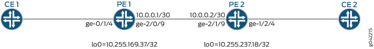
Figure 1 illustrates a simple EVPN topology with virtual switch support. Routers PE1 and PE2 are the provider edge (PE) routers that connect to one customer edge (CE) router each – CE1 and CE2.
Configuration
Procedure
CLI Quick Configuration
To quickly configure this example, copy the
following commands, paste them into a text file, remove any line breaks,
change any details necessary to match your network configuration,
and then copy and paste the commands into the CLI at the [edit] hierarchy level.
PE1
set interfaces ge-2/0/9 unit 0 family inet address 10.0.0.1/30
set interfaces ge-2/0/9 unit 0 family mpls
set interfaces ge-0/1/4 flexible-vlan-tagging
set interfaces ge-0/1/4 encapsulation flexible-ethernet-services
set interfaces ge-0/1/4 unit 0 family bridge interface-mode trunk
set interfaces ge-0/1/4 unit 0 vlan-id-list 10
set interfaces ge-0/1/4 unit 1 family bridge interface-mode trunk
set interfaces ge-0/1/4 unit 1 vlan-id-list 20
set interfaces irb unit 0 family inet address 192.168.1.1/16
set interfaces irb unit 1 family inet address 192.168.2.1/16
set interfaces lo0 unit 0 family inet address 10.255.169.37/32
set routing-options router-id 10.255.169.37
set routing-options autonomous-system 100
set routing-options forwarding-table chained-composite-next-hop ingress evpn
set protocols rsvp interface all
set protocols rsvp interface fxp0.0 disable
set protocols mpls label-switched-path PE1-to-PE2 from 10.255.169.37
set protocols mpls label-switched-path PE1-to-PE2 to 10.255.237.18
set protocols mpls interface all
set protocols mpls interface fxp0.0 disable
set protocols bgp group ibgp type internal
set protocols bgp group ibgp local-address 10.255.169.37
set protocols bgp group ibgp family evpn signaling
set protocols bgp group ibgp neighbor 10.255.237.18
set protocols ospf area 0.0.0.0 interface all
set protocols ospf area 0.0.0.0 interface fxp0.0 disable
set routing-instances evpna instance-type virtual-switch
set routing-instances evpna interface ge-0/1/4.0
set routing-instances evpna interface ge-0/1/4.1
set routing-instances evpna route-distinguisher 10.255.169.37:1
set routing-instances evpna vrf-target target:100:1
set routing-instances evpna protocols evpn extended-vlan-list [ 10 20 ]
set routing-instances evpna bridge-domains bda domain-type bridge
set routing-instances evpna bridge-domains bda vlan-id 10
set routing-instances evpna bridge-domains bda routing-interface irb.0
set routing-instances evpna bridge-domains bda bridge-options interface ge-0/1/4.0
set routing-instances evpna bridge-domains bdb domain-type bridge
set routing-instances evpna bridge-domains bdb vlan-id 20
set routing-instances evpna bridge-domains bdb routing-interface irb.1
set routing-instances evpna bridge-domains bdb bridge-options interface ge-0/1/4.1
set routing-instances vrf instance-type vrf
set routing-instances vrf interface irb.0
set routing-instances vrf interface irb.1
set routing-instances vrf route-distinguisher 198.51.100.1:2
set routing-instances vrf vrf-target target:100:2
set routing-instances vrf vrf-table-label
PE2
set interfaces ge-2/1/9 unit 0 family inet address 10.0.0.2/30
set interfaces ge-2/1/9 unit 0 family mpls
set interfaces ge-1/2/4 flexible-vlan-tagging
set interfaces ge-1/2/4 encapsulation flexible-ethernet-services
set interfaces ge-1/2/4 unit 0 family bridge interface-mode trunk
set interfaces ge-1/2/4 unit 0 vlan-id-list 10
set interfaces ge-1/2/4 unit 1 family bridge interface-mode trunk
set interfaces ge-1/2/4 unit 1 vlan-id-list 20
set interfaces irb unit 0 family inet address 192.168.2.2/16
set interfaces irb unit 1 family inet address 192.168.2.3/16
set interfaces lo0 unit 0 family inet address 10.255.237.18/32
set routing-options router-id 10.255.237.18
set routing-options autonomous-system 100
set routing-options forwarding-table chained-composite-next-hop ingress evpn
set protocols rsvp interface all
set protocols rsvp interface fxp0.0 disable
set protocols mpls label-switched-path PE2-to-PE1 from 10.255.237.18
set protocols mpls label-switched-path PE2-to-PE1 to 10.255.169.37
set protocols mpls interface all
set protocols mpls interface fxp0.0 disable
set protocols bgp group ibgp type internal
set protocols bgp group ibgp local-address 10.255.237.18
set protocols bgp group ibgp family evpn signaling
set protocols bgp group ibgp neighbor 10.255.169.37
set protocols ospf area 0.0.0.0 interface all
set protocols ospf area 0.0.0.0 interface fxp0.0 disable
set routing-instances evpna instance-type virtual-switch
set routing-instances evpna interface ge-1/2/4.0
set routing-instances evpna interface ge-1/2/4.1
set routing-instances evpna route-distinguisher 10.255.237.18:1
set routing-instances evpna vrf-target target:100:1
set routing-instances evpna protocols evpn extended-vlan-list [ 10 20 ]
set routing-instances evpna bridge-domains bda domain-type bridge
set routing-instances evpna bridge-domains bda vlan-id 10
set routing-instances evpna bridge-domains bda routing-interface irb.0
set routing-instances evpna bridge-domains bda bridge-options interface ge-1/2/4.0
set routing-instances evpna bridge-domains bdb domain-type bridge
set routing-instances evpna bridge-domains bdb vlan-id 20
set routing-instances evpna bridge-domains bdb routing-interface irb.1
set routing-instances evpna bridge-domains bdb bridge-options interface ge-1/2/4.1
set routing-instances vrf instance-type vrf
set routing-instances vrf interface irb.0
set routing-instances vrf interface irb.1
set routing-instances vrf route-distinguisher 198.51.100.2:2
set routing-instances vrf vrf-target target:100:2
set routing-instances vrf vrf-table-label
Step-by-Step Procedure
The following example requires you to navigate various levels in the configuration hierarchy. For information about navigating the CLI, see Using the CLI Editor in Configuration Mode.
To configure Router PE1:
Repeat this procedure for Router PE2, after modifying the appropriate interface names, addresses, and other parameters.
-
Configure the PE1 interfaces.
[edit interfaces]user@PE1# set ge-2/0/9 unit 0 family inet address 10.0.0.1/30 user@PE1# set ge-2/0/9 unit 0 family mpls user@PE1# set ge-0/1/4 flexible-vlan-tagging user@PE1# set ge-0/1/4 encapsulation flexible-ethernet-services user@PE1# set ge-0/1/4 unit 0 family bridge interface-mode trunk user@PE1# set ge-0/1/4 unit 0 vlan-id-list 10 user@PE1# set ge-0/1/4 unit 1 family bridge interface-mode trunk user@PE1# set ge-0/1/4 unit 1 vlan-id-list 20 user@PE1# set irb unit 0 family inet address 192.168.1.1/16 user@PE1# set irb unit 1 family inet address 192.168.2.1/16 user@PE1# set lo0 unit 0 family inet address 10.255.169.37/32 -
Set the router ID and autonomous system number for Router PE1.
[edit routing-options]
user@PE1# set router-id 10.255.169.37
user@PE1# set autonomous-system 100
-
Configure the chained composite next hop for EVPN.
[edit routing-options]
user@PE1# set forwarding-table chained-composite-next-hop ingress evpn
-
Enable RSVP on all the interfaces of Router PE1, excluding the management interface.
[edit protocols]
user@PE1# set rsvp interface all
user@PE1# set rsvp interface fxp0.0 disable
-
Create label-switched paths for PE1 to reach PE2.
[edit protocols]
user@PE1# set mpls label-switched-path PE1-to-PE2 from 10.255.169.37
user@PE1# set mpls label-switched-path PE1-to-PE2 to 10.255.237.18
-
Enable MPLS on all the interfaces of Router PE1, excluding the management interface.
[edit protocols]
user@PE1# set mpls interface all
user@PE1# set mpls interface fxp0.0 disable
-
Configure the BGP group for Router PE1.
[edit protocols]
user@PE1# set bgp group ibgp type internal
-
Assign local and neighbor addresses to the ibgp BGP group for Router PE1 to peer with Router PE2.
[edit protocols]
user@PE1# set bgp group ibgp local-address 10.255.169.37
user@PE1# set bgp group ibgp neighbor 10.255.237.18
-
Include the EVPN signaling Network Layer Reachability Information (NLRI) to the ibgp BGP group.
[edit protocols]
user@PE1# set bgp group ibgp family evpn signaling
-
Configure OSPF on all the interfaces of Router PE1, excluding the management interface.
[edit protocols]
user@PE1# set ospf area 0.0.0.0 interface all
user@PE1# set ospf area 0.0.0.0 interface fxp0.0 disable
-
Configure the virtual switch routing instance.
[edit routing-instances]
user@PE1# set evpna instance-type virtual-switch
-
Configure the interface name for the evpna routing instance.
[edit routing-instances]
user@PE1# set evpna interface ge-0/1/4.0
user@PE1# set evpna interface ge-0/1/4.1
-
Configure the route distinguisher for the evpna routing instance.
[edit routing-instances]
user@PE1# set evpna route-distinguisher 10.255.169.37:1
-
Configure the VPN routing and forwarding (VRF) target community for the evpna routing instance.
[edit routing-instances]
user@PE1# set evpna vrf-target target:100:1
-
List the VLAN identifiers that are to be EVPN extended.
[edit routing-instances]
user@PE1# set evpna protocols evpn extended-vlan-list [ 10 20 ]
-
Configure the bridge domains for the evpna routing instance.
[edit routing-instances]
user@PE1# set evpna bridge-domains bda domain-type bridge
-
Assign the VLAN ID for the bda bridge domain.
[edit routing-instances]
user@PE1# set evpna bridge-domains bda vlan-id 10
-
Configure the IRB interface as the routing interface for the bda bridge domain.
[edit routing-instances]
user@PE1# set evpna bridge-domains bda routing-interface irb.0
-
Configure the interface name for the bda bridge domain.
[edit routing-instances]
user@PE1# set evpna bridge-domains bda bridge-options interface ge-0/1/4.0
-
Configure the bridge domains for the evpna routing instance.
[edit routing-instances]
user@PE1# set evpna bridge-domains bdb domain-type bridge
-
Assign the VLAN ID for the bdb bridge domain.
[edit routing-instances]
user@PE1# set evpna bridge-domains bdb vlan-id 20
-
Configure the IRB interface as the routing interface for the bda bridge domain.
[edit routing-instances]
user@PE1# set evpna bridge-domains bdb routing-interface irb.1
-
Configure the interface name for bdb bridge domain.
[edit routing-instances]
user@PE1# set evpna bridge-domains bdb bridge-options interface ge-0/1/4.1
-
Configure the VRF routing instance.
[edit routing-instances]
user@PE1# set vrf instance-type vrf
-
Configure the IRB interface as the routing interface for the vrf routing instance.
[edit routing-instances]
user@PE1# set vrf interface irb.0
user@PE1# set vrf interface irb.1
-
Configure the route distinguisher for the vrf routing instance.
[edit routing-instances]
user@PE1# set vrf route-distinguisher 198.51.100.1:2
-
Configure the VRF target community for the vrf routing instance.
[edit routing-instances]
user@PE1# set vrf vrf-target target:100:2
-
Configure VRF label for the vrf routing instance.
[edit routing-instances]
user@PE1# set vrf vrf-table-label
Results
From configuration mode, confirm your configuration
by entering the show interfaces, show routing-options, show protocols, and show routing-instances commands. If the output does not display the intended configuration,
repeat the instructions in this example to correct the configuration.
user@PE1# show interfaces
ge-2/0/9 {
    unit 0 {
        family inet {
            address 10.0.0.1/30;
        }
        family mpls;
    }
}
ge-0/1/4 {
    flexible-vlan-tagging;
    encapsulation flexible-ethernet-services;
    unit 0 {
        family bridge {
            interface-mode trunk;
            vlan-id-list 10;
        }
    }
    unit 1 {
        family bridge {
            interface-mode trunk;
            vlan-id-list 20;
        }
    }
}
irb {
    unit 0 {
        family inet {
            address 192.168.1.1/16;
        }
    }
    unit 1 {
        family inet {
            address 192.168.2.1/16;
        }
    }
}
lo0 {
    unit 0 {
        family inet {
            address 10.255.169.37/32;
        }
    }
}
user@PE1# show routing-options
router-id 10.255.169.37;
autonomous-system 100;
forwarding-table {
    chained-composite-next-hop {
        ingress {
            evpn;
        }
    }
}
user@PE1# show protocols
rsvp {
    interface all;
    interface fxp0.0 {
        disable;
    }
}
mpls {
    label-switched-path PE1-to-PE2 {
        from 10.255.169.37;
        to 10.255.237.18;
    }
    interface all;
    interface fxp0.0 {
        disable;
    }
}
bgp {
    group ibgp {
        type internal;
        local-address 10.255.169.37;
        family evpn {
            signaling;
        }
        neighbor 10.255.237.18;
    }
}
ospf {
    area 0.0.0.0 {
        interface all;
        interface fxp0.0 {
            disable;
        }
    }
}
user@PE1# show routing-instances
evpna {
    instance-type virtual-switch;
    interface ge-0/1/4.0;
    interface ge-0/1/4.1;
    route-distinguisher 10.255.169.37:1;
    vrf-target target:100:1;
    protocols {
        evpn {
            extended-vlan-list [ 10 20 ];
        }
    }
    bridge-domains {
        bda {
            domain-type bridge;
            vlan-id 10;
            routing-interface irb.0;
            bridge-options {
                interface ge-0/1/4.0;
            }
        }
        bdb {
            domain-type bridge;
            vlan-id 20;
            routing-interface irb.1;
            bridge-options {
                interface ge-0/1/4.1;
            }
        }
    }
}
vrf {
    instance-type vrf;
    interface irb.0;
    interface irb.1;
    route-distinguisher 10.255.169.37:2;
    vrf-target target:100:2;
    vrf-table-label;
}
Verification
Confirm that the configuration is working properly.
- Verifying the Bridge Domain Configuration
- Verifying MAC Table Routes
- Verifying the Bridge EVPN Peer Gateway MAC
Verifying the Bridge Domain Configuration
Purpose
Verify the bridge domain configuration for the evpna routing instance.
Action
From operational mode, run the show bridge domain
extensive command.
user@PE1> show bridge domain extensive
Routing instance: evpna
Bridge domain: bda                            State: Active
Bridge VLAN ID: 10                            EVPN extended: Yes
Interfaces:
    ge-0/1/4.0
    pip-10.000010000000
    pip-10.feff0f000000
Total MAC count: 2

Bridge domain: bdb                            State: Active
Bridge VLAN ID: 20                            EVPN extended: Yes
Interfaces:
    ge-0/1/4.1
    pip-11.010010000000
    pip-11.ffff0f000000
Total MAC count: 2
Meaning
The configured bridge domains bda and bdb and their associated VLAN IDs and interfaces are displayed.
The bridge domains are also extended with EVPN.
Verifying MAC Table Routes
Purpose
Verify the MACs learned in the data plane and control plane.
Action
From operational mode, run the show bridge mac-table command.
user@PE1> show bridge mac-table
MAC flags (S -static MAC, D -dynamic MAC, L -locally learned, C -Control MAC
           SE -Statistics enabled, NM -Non configured MAC, R -Remote PE MAC)

Routing instance : evpna
 Bridging domain : bda, VLAN : 10
   MAC                 MAC      Logical          NH     RTR
   address             flags    interface        Index  ID
   00:00:00:aa:01:01   S        ge-0/1/4.0
   00:00:00:bb:01:01   DC                        1048574 1048574
   00:00:00:cc:01:01   DC                        1048576 1048576

Bridging domain : bdb, VLAN : 20
   MAC                 MAC      Logical          NH     RTR
   address             flags    interface        Index  ID
   00:00:00:aa:02:01   S        ge-0/1/4.1
   00:00:00:bb:02:01   DC                        1048575 1048575
   00:00:00:cc:02:01   DC                        1048577 1048577
Meaning
The configured static MACs for the bridge domains are displayed.
Verifying the Bridge EVPN Peer Gateway MAC
Purpose
Verify the bridge EVPN peer gateway MAC for the evpna routing instance.
Action
From operational mode, run the show bridge evpn
peer-gateway-macs command.
user@PE1> show bridge evpn peer-gateway-macs
Routing instance : evpna
 Bridging domain : bda, VLAN : 10
  Installed GW MAC addresses:
  00:23:9c:96:af:f0
  a8:d0:e5:5b:02:08

Bridging domain : bdb, VLAN : 20
  Installed GW MAC addresses:
  00:23:9c:96:af:f0
  a8:d0:e5:5b:02:08
Meaning
The gateway MACs of the EVPN peers for the evpna routing instance are displayed.