ON THIS PAGE
Example: Preserving Bandwidth with IGMP Snooping in an EVPN-VXLAN Environment
This example shows how to configure IGMP snooping on provider edge (PE) devices in an Ethernet VPN (EVPN)-Virtual Extensible LAN. When multicast traffic arrives at the VXLAN core, a PE device configured with EVPN forwards traffic only to the local access interfaces where there are IGMP listeners.
Requirements
This example uses the following hardware and software components:
-
Two QFX10000 switches configured as multihomed PE devices that are connected to the CE, one QFX10000 device configured as a PE device connected to the multihomed PEs and a QFX5110 configured as a CE device.
-
Junos OS Release 17.2R1 or later running on all devices.
Overview
IGMP snooping is used to constrain multicast traffic in a broadcast domain to interested receivers and multicast devices. In an environment with significant multicast traffic, IGMP snooping preserves bandwidth because multicast traffic is forwarded only on those interfaces where there are IGMP listeners. IGMP is enabled to manage multicast group membership.
When you enable IGMP snooping on each VLAN, the device advertises EVPN Type 7 and Type 8 routes (Join and Leave Sync Routes) to synchronize IGMP join and leave states among multihoming peer devices in the EVPN instance. On the access side, devices only forward multicast traffic to subscribed listeners. However, multicast traffic is still flooded in the EVPN core even when there are no remote receivers.
Configuring IGMP snooping in an EVPN-VXLAN environment requires the following:
-
Multihoming peer PE devices in all-active mode.
-
IGMP version 2 only. (IGMP versions 1 and 3 are not supported.)
-
IGMP snooping configured in proxy mode for the PE to become the IGMP querier for the local access interfaces.
This feature supports both intra-VLAN and inter-VLAN multicast
forwarding. You can configure a PE device to perform either or both.
In this example, to enable inter-VLAN forwarding, each PE device is
configured as a statically defined Protocol Independent Multicast
(PIM) rendezvous point (RP) to enable multicast forwarding. You also
configure the
distributed-dr
statement at the [edit protocols
pim interface interface-name] hierarchy
level for each IRB interface. This mode enables PIM to forward multicast
traffic more efficiently by disabling PIM features that are not required
in this scenario. When you configure this statement, PIM ignores the
designated router (DR) status of the interface when processing IGMP
reports received on the interface. When the interface receives the
IGMP report, the PE device sends PIM upstream join messages to pull
the multicast stream and forward it to the interface—regardless
of the DR status of the interface.
Topology
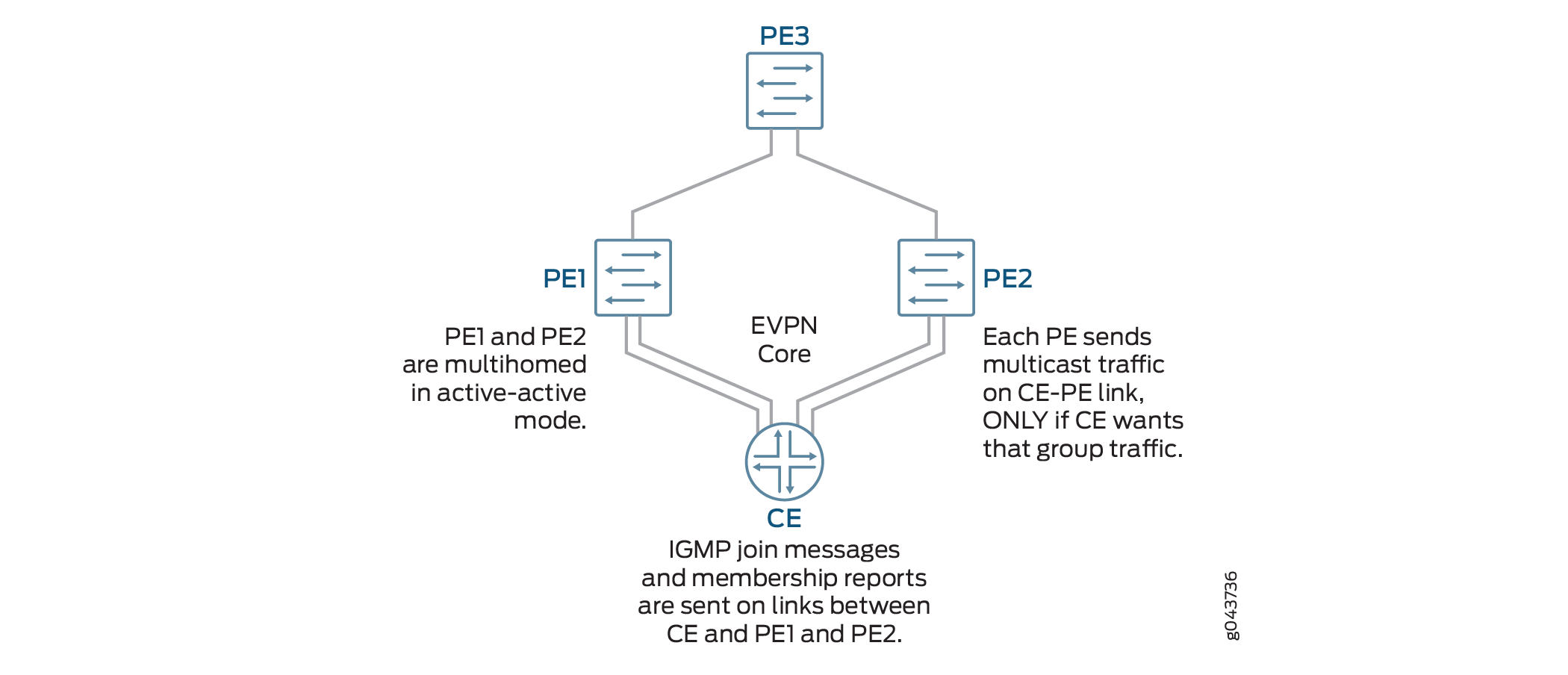
Figure 1 illustrates an EVPN-VXLAN environment where two PE devices (PE1 and PE2) are connected to the customer edge (CE) device. These PEs are dual-ihomed in active-active mode to provide redundancy. A third PE device forwards traffic to the PE devices that face the CE. IGMP is enabled on integrated routing and bridging (IRB) interfaces. The CE device hosts five VLANs; IGMP snooping is enabled on all of the VLANs. Because this implementation does not support the use of a multicast router, each VLAN in the PE is enabled as an IGMP Layer 2 querier. The multihomed PE devices forward traffic towards the CE only on those interfaces where there are IGMP listeners.
Configuration
To configure IGMP Snooping in an EVPN-VXLAN environment, perform these tasks:
CLI Quick Configuration
To quickly configure this example, copy the
following commands, paste them into a text file, remove any line breaks,
change any details necessary to match your network configuration,
copy and paste the commands into the CLI at the [edit] hierarchy
level, and then enter commit from configuration mode.
Device PE1
set chassis aggregated-devices ethernet device-count 2
set interfaces xe-0/0/0:1 description “Connected to CE”
set interfaces xe-0/0/0:2 ether-options 802.3ad ae1
set interfaces xe-0/0/1:0 enable
set interfaces xe-0/0/1:0 unit 0 description “Connected to PE3”
set interfaces xe-0/0/1:0 unit 0 family inet address 192.0.2.1/24
set interfaces ae0 enable
set interfaces ae1 enable
set interfaces lo0 unit 0 family inet address 192.168.1.1/32
set interfaces ae0 esi 00:11:11:11:11:11:11:11:11:11
set interfaces ae0 esi all-active
set interfaces ae0 aggregated-ether-options lacp active
set interfaces ae0 aggregated-ether-options lacp periodic fast
set interfaces ae0 aggregated-ether-options lacp system-id 00:00:00:00:00:01
set interfaces ae0 unit 0 description “Connected to CE”
set interfaces ae1 esi 00:22:22:22:22:22:22:22:22:22
set interfaces ae1 esi all-active
set interfaces ae1 aggregated-ether-options lacp active
set interfaces ae1 aggregated-ether-options periodic fast
set interfaces ae1 aggregated-ether-options lacp system id 00:00:00:00:00:02
set interfaces ae1 unit 0 description “Connected to CE”
set interfaces ae0 family ethernet-switching interface-mode trunk
set interfaces ae0 family ethernet-switching vlan members [ VLAN1 VLAN2 VLAN3 VLAN4 VLAN5 ]
set interfaces ae1 unit 0 family ethernet-switching interface-mode trunk
set interfaces ae1 unit 0 family ethernet-switching vlan [ VLAN1 VLAN2 VLAN3 VLAN4 VLAN5 ]
set interfaces irb unit 1 family inet address 10.1.1.1/24 virtual-gateway-address 10.1.1.10
set interfaces irb unit 2 family inet address 10.2.1.1/24 virtual-gateway-address 10.2.1.10
set interfaces irb unit 3 family inet address 10.3.1.1/24 virtual-gateway-address 10.3.1.10
set interfaces irb unit 4 family inet address 10.4.1.1/24 virtual-gateway-address 10.4.1.10
set interfaces irb unit 5 family inet address 10.5.1.1/24 virtual-gateway-address 10.5.1.10
set routing-options router-id 192.168.1.1
set routing-options autonomous-system 65536
set protocols ospf area 0.0.0.0 interface xe-0/0/1:0.0
set protocols ospf area 0.0.0.0 interface lo0.0 passive
set protocols bgp group INT type internal
set protocols bgp group INT local-address 192.168.1.1
set protocols bgp group INT family evpn signaling
set protocols bgp group INT local-as 65536
set protocols bgp group INT neighbor 172.16.1.1
set vlans VLAN vlan-id 1
set vlans VLAN1 l3-interface irb.1
set vlans VLAN1 vxlan vni 1
set vlans VLAN2 vlan-id 2
set vlans VLAN2 l3-interface irb.2
set vlans VLAN2 vxlan vni2
set vlans VLAN3 vlan-id 3
set vlans VLAN3 l3-interface irb.3
set vlans VLAN3 vxlan vni 3
set vlans VLAN4 vlan-id 4
set vlans VLAN4 l3-interface irb.4
set vlans VLAN4 vxlan vni 4
set vlans VLAN5 vlan-id 5
set vlans VLAN5 l3-interface irb.5
set vlans VLAN5 vxlan vni 5
set protocols evpn encapsulation vxlan
set protocols evpn ingress-replication
set protocols evpn extended-vni-list 1-5
set policy-options policy-statement evpn-pplb from protocol evpn
set policy-options policy-statement evpn-pplb then load-balance per-packet
set routing-options forwarding-table export evpn-pplb
set switch-options vtep-source-interface lo0:0
set switch-options route distinguisher 192.168.1.1:1
set switch-options vrf-target target:1:1
set protocols igmp interface irb.1
set protocols igmp interface irb.2
set protocols igmp interface irb.3
set protocols igmp interface irb.4
set protocols igmp interface irb.5
set protocols igmp-snooping vlan VLAN1 l2-querier source-address 10.1.1.1
set protocols igmp-snooping vlan VLAN1 proxy
set protocols igmp-snooping vlan VLAN2 l2-querier source-address 10.2.1.1
set protocols igmp-snooping vlan VLAN2 proxy
set protocols igmp-snooping vlan VLAN3 l2-querier source-address 10.3.1.1
set protocols igmp-snooping vlan VLAN3 proxy
set protocols igmp-snooping vlan VLAN4 l2-querier source-address 10.4.1.1
set protocols igmp-snooping vlan VLAN4 proxy
set protocols igmp-snooping vlan VLAN4 l2-querier source-address 10.5.1.1
set protocols igmp-snooping vlan VLAN5 proxy
set protocols pim rp static address 172.16.1.1
set protocols pim interface irb.1 distributed-dr
set protocols pim interface irb.2 distributed-dr
set protocols pim interface irb.3 distributed-dr
set protocols pim interface irb.4 distributed-dr
set protocols pim interface irb.5 distributed-dr
Device PE2
set chassis aggregated-devices ethernet device-count 2
set interfaces xe-0/0/0:0 ether-options 802.3ad ae1
set interfaces xe-0/0/0:1 description “Connected to CE”
set interfaces xe-0/0/0:1 ether-options 802.3ad ae0
set interfaces xe-0/0/1:0 enable
set interfaces xe-0/0/1:0 unit 0 description “Connected to PE3”
set interfaces xe-0/0/1:0 family inet address 198.51.100.1/24
set interfaces ae0 enable
set interfaces ae1 enable
set interfaces lo0 unit 0 family inet address 192.168.2.1/32
set interfaces ae0 esi 00:11:11:11:11:11:11:11:11:11
set interfaces ae0 esi all-active
set interfaces ae0 aggregated-ether-options lacp active
set interfaces ae0 aggregated ether-options lacp periodic fast
set interfaces ae0 aggregated ether-options lacp system-id 00:00:00:00:00:01
set interfaces ae1 esi 00:22:22:22:22:22:22:22:22:22
set interfaces ae1 esi all-active
set interfaces ae1 aggregated-ether-options lacp active
set interfaces ae1 aggregated-ether-options lacp periodic fast
set interfaces ae1 aggregated-ether-options lacp system-id 00:00:00:00:00:02
set interfaces ae0 unit 0 description “Connected to CE”
set interfaces ae0 unit family ethernet-switching interface-mode trunk
set interfaces ae0 unit family ethernet-switching vlan members [ VLAN1 VLAN2 VLAN3 VLAN4 VLAN5 ]
set interfaces ae1 unit 0 description “Connected to CE”
set interfaces ae1 unit 0 family ethernet-switching interface-mode trunk
set interfaces ae1 unit 0 family ethernet-switching vlan members [ VLAN1 VLAN2 VLAN3 VLAN4 VLAN5 ]
set interfaces irb unit 1 family inet address 10.1.1.2/24 virtual-gateway-address 10.1.1.10
set interfaces irb unit 2 family inet address 10.2.1.2/24 virtual-gateway-address 10.2.1.10
set interfaces irb unit 3 family inet address 10.3.1.2/24 virtual-gateway-address 10.3.1.10
set interfaces irb unit 4 family inet address 10.4.1.2/24 virtual-gateway-address 10.4.1.10
set interfaces irb unit 5 family inet address 10.5.1.2/24 virtual-gateway-address 10.5.1.10
set routing-options router-id 192.168.2.1
set routing-options autonomous-system 65536
set protocols ospf area 0.0.0.0 interface lo0.0 passive
set protocols ospf area 0.0.0.0 interface xe-0/0/1:0.0
set protocols bgp group INT type internal
set protocols bgp group INT local-address 192.168.2.1
set protocols bgp group INT family evpn signaling
set protocols bgp group INT local-as 65536
set protocols bgp group INT neighbor 172.16.1.1
set vlans VLAN1 vlan-id 1
set vlans VLAN1 l3-interface irb.1
set vlans VLAN1 vxlan vni 1
set vlans VLAN2 vlan-id 2
set vlans VLAN2 l3-interface irb.2
set vlans VLAN2 vxlan vni 2
set vlans VLAN3 vlan-id 3
set vlans VLAN3 l3-interface irb.3
set vlans VLAN3 vxlan vni 3
set vlans VLAN4 vlan-id 4
set vlans VLAN4 l3-interface irb.4
set vlans VLAN4 vxlan vni 4
set vlans VLAN5 vlan-id 5
set vlans VLAN5 l3-interface irb.5
set vlans VLAN5 vxlan vni 3
set protocols evpn encapsulation vxlan
set protocols evpn muticast-mode ingress-encapsulation
set protocols evpn extended-vni-list 1-5
set policy-options policy statement evpn-pplb from protocol evpn
set policy-options policy-statement evpn-pplb then load-balance per-packet
set routing-options forwarding-table export evpn-pplb
set switch-options vtep-source-interface lo0.0
set switch-options route-distinguisher 192.168.2.1:1
set switch-options vrf-target target:1:1
set protocols igmp interface irb.1
set protocols igmp interface irb.2
set protocols igmp interface irb.3
set protocols igmp interface irb.4
set protocols igmp interface irb.5
set protocols igmp-snooping vlan VLAN1 l2-querier source-address 10.1.1.2
set protocols igmp-snooping vlan VLAN1 proxy
set protocols igmp-snooping vlan VLAN2 l2-querier source-address 10.2.1.2
set protocols igmp-snooping vlan VLAN2 proxy
set protocols igmp-snooping vlan VLAN3 l2-querier source-address 10.3.1.2
set protocols igmp-snooping vlan VLAN3 proxy
set protocols igmp-snooping vlan VLAN4 l2-querier source-address 10.4.1.2
set protocols igmp-snooping vlan VLAN4 proxy
set protocols igmp-snooping vlan VLAN5 l2-querier source-address 10.5.1.2
set protocols igmp-snooping vlan VLAN5 proxy
set protocols pim rp static address 172.16.1.1
set protocols pim interface irb.1 distributed-dr
set protocols pim interface irb.2 distributed-dr
set protocols pim interface irb.3 distributed-dr
set protocols pim interface irb.4 distributed-dr
set protocols pim interface irb.5 distributed-dr
CE
set chassis aggregated devices ethernet device-count 2
set interfaces xe-0/2/0 ether-options 802.3ad ae0
set interfaces xe-0/2/1 ether-options 802.3ad ae0
set interfaces xe-0/2/0 unit 0 family ethernet-switching interface-mode trunk
set interfaces xe-0/2/0 unit 0 family ethernet-switching vlan members 1-5
set interfaces xe-0/2/1 unit 0 family ethernet-switching interface-mode trunk
set interfaces xe-0/2/1 unit 0 family ethernet-switching vlan members 1-5
set interfaces ae0 aggregated-ether-options lacp active
set interfaces ae0 aggregated-ether-options lacp periodic fast
set interfaces ae0 unit 0 family ethernet-switching interface-mode trunk
set interfaces ae0 unit 0 family ethernet-switching vlan members 1-5
set interfaces ae1 aggregated-ether-options lacp active
set interfaces ae1 aggregated-ether-options lacp periodic fast
set interfaces ae1 unit 0 family ethernet-switching interface-mode trunk
set interfaces ae1 unit 0 family ethernet-switching vlan members 1-5
set vlans BD-1 vlan-id 1
set vlans BD-2 vlan-id 2
set vlans BD-3 vlan-id 3
set vlans BD-4 vlan-id 4
set vlans BD-5 vlan-id 5
PE3
set interfaces xe-0/0/0 enable
set interfaces xe-/0/0/0 unit 0 description “Connected to PE1”
set interfaces xe-0/0/0 unit 0 family inet 192.0.2.2/24
set interfaces xe-0/0/1 enable
set interfaces xe-0/0/1 unit 0 description “Connected to PE2”
set interfaces xe-0/0/1 unit 0 family inet 198.51.100.2/24
set interfaces lo0 unit 0 family inet address 172.16.1.1/32
set interfaces xe-0/0/0:1 enable
set interfaces xe-0/0/0:1 unit 0 family ethernet-switching interface-mode trunk
set interfaces xe-0/0/0:1 unit 0 family ethernet-switching vlan members [ VLAN1 VLAN2 VLAN3 VLAN4 VLAN5 ]
set interfaces xe-0/0/1:1 enable
set interfaces xe-0/0/1:1 unit 0 family ethernet-switching interface-mode trunk
set interfaces xe-0/0/1:1 unit 0 family ethernet-switching vlan members [ VLAN1 VLAN2 VLAN3 VLAN4 VLAN5 ]
set interfaces irb unit 1 famly inet address 10.1.1.5/24 virtual-gateway address 10.1.1.10
set interfaces irb unit 2 family inet address 10.2.1.5/24 virtual-gateway address 10.2.1.10
set interfaces irb unit 3 family inet address 10.3.1.5/24 virtual-gateway address 10.3.1.10
set interfaces irb unit 4 family inet address 10.4.1.5/24 virtual-gateway address 10.4.1.10
set interrfaces irb unit 5 family inet address 10.5.1.5/24 virtual-gateway address 10.5.1.10
set routing-options router-id  172.16.1.1
se routing-options autonomous-system 65536
set ospf area 0.0.0.0 interface all
set ospf area 0.0.0.0 fxp0.0 disable
set protocols bgp group INT type internal
set protocols bgp group INT  local-address 172.16.1.1
set protocols bgp group INT family evpn signaling
set protocols bgp group INT local-as 65536
set protocols bgp group INT neighbor 192.168.1.1
set protocols bgp group INT neighbor 192.168.2.1
set vlans VLAN1 vlan-id 1
set vlans VLAN1 l3-interface irb.1
set vlans VLAN1 vxlan vni 1
set vlans VLAN2 vlan-id 2
set vlans VLAN2 l3-interface irb.2
set vlans VLAN2 vxlan vni 2
set vlans VLAN3 vlan-id 3
set vlans VLAN3 l3-interface irb.3
set vlans VLAN3 vxlan vni 3
set vlans VLAN4 vlan-id 4
set vlans VLAN4 l3-interface irb.4
set vlans VLAN4 vxlan vni 4
set vlans VLAN5 vlan-id 5
set vlans VLAN5 l3-interface irb.5
set vlans VLAN5 vxlan vni 5
set protocols evpn encapsulation vxlan
set protocols evpn multicast-mode ingress-replication
set protocols evpn extended-vni-list 1-5
set policy-options policy-statement evpn-pplb from protocol evpn
set policy-options policy-statement evpn-pbllb then load-balance per packet
set routing-options forwarding-table export evpn-pplb
set switch-options vtep-source-interface lo0
set switch-options route-distinguisher 172.16.1.1:1
set switch-option vrf-target target:1:1
set protocols igmp interface irb.1
set protocols igmp interface irb.2
set protocols igmp interface irb.3
set protocols igmp interface irb.4
set protocols igmp interface irb.5
set protocols igmp-snooping vlan VLAN1 l2-querier source-address 10.1.1.5
set protocols igmp-snooping vlan VLAN1 proxy
set protocols igmp-snooping vlan VLAN2 l2-querier source-address 10.2.1.5
set protocols igmp-snooping vlan VLAN2 proxy
set protocols igmp-snooping vlan VLAN3 l2-querier source-address 10.3.1.5
set protocols igmp-snooping vlan VLAN3 proxy
set protocols igmp-snooping vlan VLAN4 l2-querier source-address 10.4.1.5
set protocols igmp-snooping vlan VLAN4 proxy
set protocols igmp-snooping vlan VLAN5 l2-querier source-address 10.5.1.5
set protocols igmp-snooping vlan VLAN5 proxy
set protocols pim rp local 172.16.1.1
set protocols pim interface irb.1 distributed-dr
set protocols pim interface irb.2 distributed-dr
set protocols pim interface irb.3 distributed-dr
set protocols pim interface irb.4 distributed-dr
set protocols pim interface irb.5 distributed-dr
Configuring PE1
Step-by-Step Procedure
The following example requires you to navigate various levels in the configuration hierarchy. For information about navigating the CLI, see Using the CLI Editor in Configuration Mode in the CLI User Guide.
To configure device PE1:
-
Specify the number of aggregated Ethernet logical interfaces.
[edit chassis] user@PE1# set aggregated-devices ethernet device-count 2 -
Configure the interfaces.
[edit interfaces]
user@PE1# set xe-0/0/0:1 description “Connected to CE”
user@PE1# set xe-0/0/0:2 ether-options 802.3ad ae1
user@PE1# set xe-0/0/1:0 enable
user@PE1# set xe-0/0/1:0 unit 0 description “Connected to PE3”
user@PE1# set xe-0/0/1:0 unit 0 family inet address 192.0.2.1/24
user@PE1# set ae0 enable
user@PE1# set ae1 enable
user@PE2# set lo0 unit 0 family inet address 192.168.1.1/32
-
Configure active-active multihoming and enable the Link Aggregation Control Protocol (LACP) on each aggregated Ethernet interface.
[edit interfaces]
user@PE1# set ae0 esi 00:11:11:11:11:11:11:11:11:11
user@PE1# set esi all-active
user@PE1# set ae0 aggregated-ether-options lacp active
user@PE1# set ae0 aggregated-ether-options lacp periodic-fast
user@PE1# set ae0 aggregated-ether-options lacp system-id 00:00:00:00:00:01
user@PE1# set ae1 esi 00:22:22:22:22:22:22:22:22:22
user@PE1# set ae1 esi all-active
user@PE1# set ae1 aggregated-ether-options lacp active
user@PE1# set ae1 aggregated-ether-options lacp periodic-fast
user@PE1# set ae0 aggregated-ether-options lacp system-id 00:00:00:00:00:02
-
Configure each aggregated Ethernet interface as a trunk port.
[edit interfaces]
user@PE1# set ae0 unit 0 description “Connected to CE”
user@PE1# set ae0 unit 0 family ethernet-switching interface-mode trunk
user@PE1# set ae0 unit 0 family ethernet-switching vlan members [ VLAN1 VLAN2 VLAN3 VLAN4 VLAN5 ]
user@PE1# set ae1 unit 0 description “Connected to CE”
user@PE1# set ae1 unit 0 family ethernet-switching interface-mode trunk
user@PE1# set ae1 unit 0 family ethernet-switching vlan members [ VLAN1 VLAN2 VLAN3 VLAN4 VLAN5 ]
-
Configure IRB interfaces and virtual-gateway addresses.
[edit interfaces]
user@PE1# set irb unit 1 family inet address 10.1.1.1/24 virtual-gateway-address 10.1.1.10
user@PE1# set irb unit 2 family inet address 10.2.1.1/24 virtual-gateway-address 10.2.1.10
user@PE1# set irb unit 3 family inet address 10.3.1.1/24 virtual-gateway-address 10.3.1.10
user@PE1# set irb unit 4 family inet address 10.4.1.1/24 virtual-gateway-address 10.4.1.10
user@PE1# set irb unit 5 family inet address 10.5.1.1/24 virtual-gateway-address 10.5.1.10
-
Configure the autonomous system.
[edit routing-options]
user@PE1# set router-id 192.168.1.1
user@PE1# set autonomous-system 65536
-
Configure OSPF.
[edit protocols ospf]
user@PE1# set area 0.0.0.0 interface xe-0/0/1:0.0
user@PE1# set area 0.0.0.0 interface lo0. passive
-
Configure BGP internal peering.
[edit protocols bgp]
user@PE1# set group INT type internal
user@PE1# set group INT local-address 192.168.1.1
user@PE1# set group INT family evpn signaling
user@PE1# set group INT local-as 65536
user@PE1# set group INT neighbor 172.16.1.1
-
Configure the VLANs.
[set vlans]
user@PE1# set VLAN1 vlan-id 1
user@PE1# set VLAN1 l3-interface irb.1
user@PE1# set VLAN1 vxlan vni 1
user@PE1# set VLAN2 vlan-id 2
user@PE1# set VLAN2 l3-interface irb.2
user@PE1# set VLAN2 vxlan vni 2
user@PE1# set VLAN3 vlan-id 3
user@PE1# set VLAN3 l3-interface irb.3
user@PE1# set VLAN3 vxlan vni 3
user@PE1# set VLAN4 vlan-id 4
user@PE1# set VLAN4 l3-interface irb.4
user@PE1# set VLAN4 vxlan vni 4
user@PE1# set VLAN5 vlan-id 5
user@PE1# set VLAN5 l3-interface irb.5
user@PE1# set VLAN2 vxlan vni 5
-
Enable EVPN.
[edit protocols evpn]
user@PE1# set encapsulation vxlan
user@PE1# set multicast-mode ingress-replication
user@PE1# set extended-vni-list 1-5
-
Configure an export routing policy to load balance EVPN traffic.
[edit policy-options]
user@PE1# set policy-statement evpn-pplb from protocol evpn
user@PE1# set policy-statement evpn-pplb then load-balance per packet

[edit routing-options]
user@PE1# set forwarding-table export evpn-pplb
-
Configure the source interface for the VXLAN tunnel.
[edit switch-options]
user@PE1# set vtep-source-interface lo0.0
user@PE1# set route-distinguisher 192.168.1.1:1
user@PE1# set vrf-target target:1:1
-
Enable IGMP on the IRB interfaces associated with the VLANs.
[edit protocols igmp]
user@PE1# set interface irb.1
user@PE1# set interface irb.2
user@PE1# set interface irb.3
user@PE1# set interface irb.4
user@PE1# set interface irb.5
-
Enable IGMP snooping on the VLANs.
[edit protocols igmp-snooping vlan]
user@PE1# set VLAN1 l2-querier source-address 10.1.1.1
user@PE1# set VLAN1 proxy
user@PE1# set VLAN2 l2-querier source-address 10.2.1.1
user@PE1# set VLAN2 proxy
user@PE1# set VLAN3 l2-querier source address 10.3.1.1
user@PE1# set VLAN3 proxy
user@PE1# set VLAN4 l2-querier source-address 10.4.1.1
user@PE1# set VLAN4 proxy
user@PE1# set VLAN5 l2-querier source-address 10.5.1.1
user@PE1# set VLAN5 proxy
-
Configure PIM by defining a static rendezvous point and enabling on the IRB interfaces associated with the VLANs..
Note:This step is required only if you want to configure inter-VLAN forwarding. If your PE device is performing only intra-VLAN forwarding, omit this step.
[edit protocols pim]
user@PE1# set rp static address 172.16.1.1
user@PE1# set interface irb.1 distrbuted-dr
user@PE1# set interface irb.2 distributed-dr
user@PE1# set interface irb.3 distributed-dr
user@PE1# set interface irb.4 distributed-dr
user@PE1# set interface irb.5 distributed-dr
Results
From configuration mode, confirm your configuration
by entering the show chassis, show interfaces. show routing-options,show protocols, show vlans, show policy-options, and show switch-options commands. If the output does not display the intended configuration,
repeat the instructions in this example to correct the configuration.
user@PE1# show chassis
aggregated-devices {
    ethernet {
        device-count 2;
    }
}
user@PE1# show
interfaces {
    xe-0/0/0:1 {
        description "Connected to CE";
        ether-options {
            802.3ad ae0;
        }
    }
    xe-0/0/0:2 {
        ether-options {
            802.3ad ae1;
        }
    }
    xe-0/0/1:0 {
        enable;
        unit 0 {
            description "Connected to PE3";
            family inet {
                address 192.0.2.1/24;
            }
        }
    }
    xe-0/0/1:1 {
        enable;
    }
    ae0 {
        enable;
        esi {
            00:11:11:11:11:11:11:11:11:11;
            all-active;
        }
        aggregated-ether-options {
            lacp {
                active;
                periodic fast;
                system-id 00:00:00:00:00:01;
            }
        }
        unit 0 {
            description "Connected to CE";
            family ethernet-switching {
                interface-mode trunk;
                vlan {
                    members [ VLAN1 VLAN2 VLAN3 VLAN4 VLAN5 ];
                }
            }
        }
    }
    ae1 {
        enable;
        esi {
            00:22:22:22:22:22:22:22:22:22;
            all-active;
        }
        aggregated-ether-options {
            lacp {
                active;
                periodic fast;
                system-id 00:00:00:00:00:02;
            }
        }
        unit 0 {
            description "Connected to CE";
            family ethernet-switching {
                interface-mode trunk;
                vlan {
                    members [ VLAN1 VLAN2 VLAN3 VLAN4 VLAN5 ];
                }
            }
        }
    }
    irb {
        unit 1 {
            family inet {
                address 10.1.1.1/24 {
                    virtual-gateway-address 10.1.1.10;
                }
            }
        }
        unit 2 {
            family inet {
                address 10.2.1.1./24 {
                    virtual-gateway-address 10.2.1.10;
                }
            }
        }
        unit 3 {
            family inet {
                address 10.3.1.1./24 {
                    virtual-gateway-address 10.3.1.10;
                }
            }
        }
        unit 4 {
            family inet {
                address 10.4.1.1./24 {
                    virtual-gateway-address 10.4.1.10;
                }
            }
        }
        unit 5 {
            family inet {
                address 10.5.1.1./24 {
                    virtual-gateway-address 10.5.1.10;
                }
            }
        }
    }
    lo0 {
        unit 0 {
            family inet {
                address 192.168.1.1/32;
            }
        }
    }
}
routing-options {
    router-id  192.168.1.1;
    autonomous-system 65536;
    forwarding-table {
        export evpn-pplb;
    }
}
protocols {
    igmp {
        interface irb.1;
        interface irb.2;
        interface irb.3;
        interface irb.4;
        interface irb.5;
    }
    bgp {
        group INT {
            type internal;
            local-address 192.168.1.1;
            family evpn {
                signaling;
            }
            local-as 65536;
            neighbor 172.16.1.1;
        }
    }
    ospf {
        area 0.0.0.0 {
            interface xe-0/0/1:0.0;
            interface lo0.0 {
                passive;
            }
        }
    }
    pim {
        rp {
            static {
                address 172.16.1.1;
            }
        }
        interface irb.1 {
            distributed-dr;
        }
        interface irb.2 {
            distributed-dr;
        }
        interface irb.3 {
            distributed-dr;
        }
        interface irb.4 {
            distributed-dr;
        }
        interface irb.5 {
            distributed-dr;
        }
    }
    evpn {
        encapsulation vxlan;
        multicast-mode ingress-replication;
        extended-vni-list 1-5;
    }
    igmp-snooping {
        vlan VLAN1 {
            l2-querier {
                source-address 10.1.1.1;
            }
            proxy;
        }
        vlan VLAN2 {
            l2-querier {
                source-address 10.2.1.1;
            }
            proxy;
        }
        vlan VLAN3 {
            l2-querier {
                source-address 10.3.1.1;
            }
            proxy;
        }
        vlan VLAN4 {
            l2-querier {
                source-address 10.4.1.1;
            }
            proxy;
        }
        vlan VLAN5 {
            l2-querier {
                source-address 10.5.1.1;
            }
            proxy;
        }
    }
}
policy-options {
    policy-statement evpn-pplb {
        from protocol evpn;
        then {
            load-balance per-packet;
        }
    }
}
switch-options {
    vtep-source-interface lo0.0;
    route-distinguisher 192.168.1.1:1;
    vrf-target target:1:1;
}
vlans {
    VLAN1 {
        vlan-id 1;
        l3-interface irb.1;
        vxlan {
            vni 1;
        }
    }
    VLAN2 {
        vlan-id 2;
        l3-interface irb.2;
        vxlan {
            vni 2;
        }
    }
    VLAN3 {
        vlan-id 3;
        l3-interface irb.3;
        vxlan {
            vni 3;
        }
    }
    VLAN4 {
        vlan-id 4;
        l3-interface irb.4;
        vxlan {
            vni 4;
        }
    }
    VLAN5 {
        vlan-id 5;
        l3-interface irb.5;
        vxlan {
            vni 5;
        }
    }
}
Configuring PE2
Step-by-Step Procedure
The following example requires you to navigate various levels in the configuration hierarchy. For information about navigating the CLI, see Using the CLI Editor in Configuration Mode in the CLI User Guide.
To configure device PE2:
-
Specify the number of aggregated Ethernet logical interfaces.
[edit chassis]
user@PE2# set aggregated-devices ethernet device-count 2
-
Configure the interfaces.
[edit interfaces]
user@PE2# set xe-0/0/0:0 ether-options 802.3ad ae1
user@PE2# set xe-0/0/0:1 description “Connected to CE”
user@PE2# set xe-0/0/1:0 enable
user@PE2# set xe-0/0/1:0 unit 0 description “Connected to PE3”
user@PE2# set xe-0/0/1:0 unit 0 family inet address 198.51.100.1/24
user@PE2# set ae0 enable
user@PE2# set ae1 enable
user@PE2# set lo0 unit 0 family inet address 192.168.2.1/32
-
Configure active-active multihoming and enable the Link Aggregation Control Protocol (LACP) on each aggregated Ethernet interface.
[edit interfaces]
user@PE2# set ae0 esi 00:11:11:11:11:11:11:11:11:11
user@PE2# set esi all-active
user@PE2# set ae0 aggregated-ether-options lacp active
user@PE2# set ae0 aggregated-ether-options lacp periodic-fast
user@PE2# set ae0 aggregated-ether-options lacp system-id 00:00:00:00:00:01
user@PE2# set ae1 esi 00:22:22:22:22:22:22:22:22:22
user@PE2# set ae1 esi all-active
user@PE2# set ae1 aggregated-ether-options lacp active
user@PE2# set ae1 aggregated-ether-options lacp periodic-fast
user@PE2# set ae0 aggregated-ether-options lacp system-id 00:00:00:00:00:02
-
Configure each aggregated Ethernet interface as a trunk port.
[edit interfaces]
user@PE2# set ae0 unit 0 description “Connected to CE”
user@PE2# set ae0 unit 0 family ethernet-switching interface-mode trunk
user@PE2# set ae0 unit 0 family ethernet-switching vlan members [ VLAN1 VLAN2 VLAN3 VLAN4 VLAN5 ]
user@PE2# set ae1 unit 0 description “Connected to CE”
user@PE2# set ae1 unit 0 family ethernet-switching interface-mode trunk
user@PE2# set ae1 unit 0 family ethernet-switching vlan members [ VLAN1 VLAN2 VLAN3 VLAN4 VLAN5 ]
-
Configure IRB interfaces and virtual-gateway addresses.
[edit interfaces]
user@PE2# set irb unit 1 family inet address 10.1.1.2/24 virtual-gateway-address 10.1.1.10
user@PE2# set irb unit 2 family inet address 10.2.1.2/24 virtual-gateway-address 10.2.1.10
user@PE2# set irb unit 3 family inet address 10.3.1.2/24 virtual-gateway-address 10.3.1.10
user@PE2# set irb unit 4 family inet address 10.4.1.2/24 virtual-gateway-address 10.4.1.10
user@PE2# set irb unit 5 family inet address 10.5.1.2/24 virtual-gateway-address 10.5.1.10
-
Configure the autonomous system.
[edit routing-options]
user@PE2# set router-id 192.168.2.1
user@PE2# set autonomous-system 65536
-
Configure OSPF.
[edit protocols ospf]
user@PE2# set area 0.0.0.0 interface xe-0/0/1:0.0
user@PE2# set area 0.0.0.0 interface lo0. passive
-
Configure BGP internal peering.
[edit protocols bgp]
user@PE2# set group INT type internal
user@PE2# set group INT local-address 192.168.2.1
user@PE2# set group INT family evpn signaling
user@PE2# set group INT local-as 65536
user@PE2# set group INT neighbor 172.16.1.1
-
Configure the VLANs.
[edit vlans]
user@PE2# set VLAN1 vlan-id 1
user@PE2# set VLAN1 l3-interface irb.1
user@PE2# set VLAN1 vxlan vni 1
user@PE2# set VLAN2 vlan-id 2
user@PE2# set VLAN2 l3-interface irb.2
user@PE2# set VLAN2 vxlan vni 2
user@PE2# set VLAN3 vlan-id 3
user@PE2# set VLAN3 l3-interface irb.3
user@PE2# set VLAN3 vxlan vni 3
user@PE2# set VLAN4 vlan-id 4
user@PE2# set VLAN4 l3-interface irb.4
user@PE2# set VLAN4 vxlan vni 4
user@PE2# set VLAN5 vlan-id 5
user@PE2# set VLAN5 l3-interface irb.5
user@PE2# set VLAN2 vxlan vni 5
-
Enable EVPN.
[edit protocols evpn]
user@PE2# set encapsulation vxlan
user@PE2# set multicast-mode ingress-replication
user@PE2# set extended-vni-list 1-5
-
Configure an export routing policy to load balance EVPN traffic and apply it to the forwarding-table.
[edit policy-options]
user@PE2# set policy-statement evpn-pplb from protocol evpn
user@PE2# set policy-statement evpn-pplb then load-balance per packet

[edit routing-options]
user@PE2# set forwarding-table export evpn-pplb
-
Configure the source interface for the VXLAN tunnel.
[edit switch-options]
user@PE2# set vtep-source-interface lo0.0
user@PE2# set route-distinguisher 192.168.2.1:1
user@PE2# set vrf-target target:1:1
-
Enable IGMP on the IRB interfaces.
[edit protocols igmp]
user@PE2# set interface irb.1
user@PE2# set interface irb.2
user@PE2# set interface irb.3
user@PE2# set interface irb.4
user@PE2# set interface irb.5
-
Enable IGMP snooping on the IRB interfaces.
[edit protocols igmp-snooping vlan]
user@PE2# set VLAN1 l2-querier source-address 10.1.1.2
user@PE2# set VLAN1 proxy
user@PE2# set VLAN2 l2-querier source-address 10.2.1.2
user@PE2# set VLAN2 proxy
user@PE2# set VLAN3 l2-querier source address 10.3.1.2
user@PE2# set VLAN3 proxy
user@PE2# set VLAN4 l2-querier source-address 10.4.1.2
user@PE2# set VLAN4 proxy
user@PE2# set VLAN5 l2-querier source-address 10.5.1.2
user@PE2# set VLAN5 proxy
-
Configure PIM by defining a static rendezvous point and enabling on the IRB interfaces.
Note:This step is required only if you want to configure inter-VLAN forwarding. If your PE device is performing only intra-VLAN forwarding, omit this step.
[edit protocols pim]
user@PE2# set rp static address 172.16.1.1
user@PE2# set interface irb.1 distrbuted-dr
user@PE2# set interface irb.2 distributed-dr
user@PE2# set interface irb.3 distributed-dr
user@PE2# set interface irb.4 distributed-dr
user@PE2# set interface irb.5 distributed-dr
Results
From configuration mode, confirm your configuration
by entering the show chassis, show interfaces. show routing-options,show protocols, show vlans, show policy-options, and show switch-options commands. If the output does not display the intended configuration,
repeat the instructions in this example to correct the configuration.
user@PE2# show chassis
aggregated-devices {
    ethernet {
        device-count 2;
    }
}
user@PE2# show
interfaces {
    xe-0/0/0:0 {
        ether-options {
            802.3ad ae1;
        }
    }
    xe-0/0/0:1 {
        description "Connected to CE";
        ether-options {
            802.3ad ae0;
        }
    }
    xe-0/0/1:0 {
        enable;
        unit 0 {
            description "Connected to PE3";
            family inet {
                address 198.51.100.1/24;
            }
        }
    }
    ae0 {
        esi {
            00:11:11:11:11:11:11:11:11:11;
            all-active;
        }
        aggregated-ether-options {
            lacp {
                active;
                periodic fast;
                system-id 00:00:00:00:00:01;
            }
        }
        unit 0 {
            description "Connected to CE";
            family ethernet-switching {
                interface-mode trunk;
                vlan {
                    members [ VLAN1 VLAN2 VLAN3 VLAN4 VLAN5 ];
                }
            }
        }
    }
    ae1 {
        enable;
        esi {
            00:22:22:22:22:22:22:22:22:22;
            all-active;
        }
        aggregated-ether-options {
            lacp {
                active;
                periodic fast;
                system-id 00:00:00:00:00:02;
            }
        }
        unit 0 {
            description "CONNECTED TO CE";
            family ethernet-switching {
                interface-mode trunk;
                vlan {
                    members [ VLAN1 VLAN2 VLAN3 VLAN4 VLAN5 ];
                }
            }
        }
    }
    irb {
        unit 1 {
            family inet {
                address 10.1.1.2/24 {
                    virtual-gateway-address 10.1.1.10;
                }
            }
        }
        unit 2 {
            family inet {
                address 10.2.1.2/24 {
                    virtual-gateway-address 10.2.1.10;
                }
            }
        }
        unit 3 {
            family inet {
                address 10.3.1.2/24 {
                    virtual-gateway-address 10.3.1.10;
                }
            }
        }
        unit 4 {
            family inet {
                address 10.4.1.2/24 {
                    virtual-gateway-address 10.4.1.10;
                }
            }
        }
        unit 5 {
            family inet {
                address 10.5.1.2/24 {
                    virtual-gateway-address 10.5.1.10;
                }
            }
        }
    }
    lo0 {
        unit 0 {
            family inet {
                address 192.168.2.1/32;
            }
        }
    }
}
routing-options {
    router-id 192.168.2.1;
    autonomous-system 65536;
    forwarding-table {
        export evpn-pplb;
    }
}
protocols {
    igmp {
        interface irb.1;
        interface irb.2;
        interface irb.3;
        interface irb.4;
        interface irb.5;
    }
    bgp {
        group INT {
            type internal;
            local-address 192.168.2.1;
            family evpn {
                signaling;
            }
            local-as 65536;
            neighbor 172.16.1.1;
        }
    }
    ospf {
        area 0.0.0.0 {
            interface lo0.0 {
                passive;
            }
            interface xe-0/0/1:0.0;
        }
    }
    pim {
        rp {
            static {
                address 172.16.1.1;
            }
        }
        interface irb.1 {
            distributed-dr;
        }
        interface irb.2 {
            distributed-dr;
        }
        interface irb.3 {
            distributed-dr;
        }
        interface irb.4 {
            distributed-dr;
        }
        interface irb.5 {
            distributed-dr;
        }
    }
    evpn {
        encapsulation vxlan;
        multicast-mode ingress-replication;
        extended-vni-list 1-5;
    }
    igmp-snooping {
        vlan VLAN1 {
            l2-querier {
                source-address 10.1.1.2;
            }
            proxy;
        }
        vlan VLAN2 {
            l2-querier {
                source-address 10.2.1.2;
            }
            proxy;
        }
        vlan VLAN3 {
            l2-querier {
                source-address 10.3.1.2;
            }
            proxy;
        }
        vlan VLAN4 {
            l2-querier {
                source-address 10.4.1.2;
            }
            proxy;
        }
        vlan VLAN5 {
            l2-querier {
                source-address 10.5.1.2;
            }
            proxy;
        }
    }
}
policy-options {
    policy-statement evpn-pplb {
        from protocol evpn;
        then {
            load-balance per-packet;
        }
    }
}
switch-options {
    vtep-source-interface lo0.0;
    route-distinguisher 192.168.2.1:1;
    vrf-target target:1:1;
}
vlans {
    VLAN1 {
        vlan-id 2;
        l3-interface irb.2;
        vxlan {
            vni 2;
        }
    }
    VLAN2 {
        vlan-id 1;
        l3-interface irb.1;
        vxlan {
            vni 1;
        }
    }
    VLAN3 {
        vlan-id 3;
        l3-interface irb.3;
        vxlan {
            vni 3;
        }
    }
    VLAN4 {
        vlan-id 4;
        l3-interface irb.4;
        vxlan {
            vni 4;
        }
    }
    VLAN5 {
        vlan-id 5;
        l3-interface irb.5;
        vxlan {
            vni 5;
        }
    }
}
Configuring CE Device
Step-by-Step Procedure
The following example requires you to navigate various levels in the configuration hierarchy. For information about navigating the CLI, see Using the CLI Editor in Configuration Mode in the CLI User Guide.
To configure device CE:
-
Specify the number of aggregated Ethernet logical interfaces.
[edit chassis]
user@CE# set aggregated-devices ethernet device-count 2
-
Configure the interfaces and enable LACP on the aggregated Ethernet interfaces.
[edit interfaces]
user@CE# set xe-0/2/0 ether-options 802.3ad ae0
user@CE# set xe-0/2/1 ether-options 802.3ad ae0
user@CE# set ae0 aggregated ether-options lacp active
user@CE# set ae0 aggregated ether-options lacp periodic fast
user@CE# set ae1 aggregated ether-options lacp active
user@CE# set ae1 aggregated ether-options lacp periodic fast
-
Create the Layer 2 customer bridge domains and the VLANs associated with the domains.
[edit]
user@CE# set vlans BD-1 vlan-id 1
user@CE# set vlans BD-2 vlan-id 2
user@CE# set vlans BD-3 vlan-id 3
user@CE# set vlans BD-4 vlan-id 4
user@CE# set vlans BD-5 vlan-id 5
-
Configure each interface to include in CE domain as a trunk port for accepting packets tagged with the specified VLAN identifiers.
[edit interfaces]
user@CE# set xe-0/2/0 unit 0 family ethernet-switching interface-mode trunk
user@CE# set xe-0/2/0 unit 0 family ethernet-switching vlan members 1-5
user@CE# set xe-0/2/1 unit 0 family ethernet-switching interface-mode trunk
user@CE# set xe-0/2/1 unit 0 family ethernet-switching vlan members 1-5
user@CE# set ae0 unit 0 family ethernet-switching interface-mode trunk
user@CE# set ae0 unit 0 family ethernet-switching vlan members 1-5
user@CE# set ae1 unit 0 family ethernet-switching interface-mode trunk
user@CE# set ae1 unit 0 family ethernet-switching vlan members 1-5
Results
From configuration mode, confirm your configuration
by entering the show chassis and show interfaces commands. If the output
does not display the intended configuration, repeat the instructions
in this example to correct the configuration.
user@CE# show chassis
aggregated-devices {
    ethernet {
        device-count 2;
    }
}
user@CE# show interfaces
xe-0/2/0 {
    ether-options {
        802.3ad ae0;
    }
    unit 0 {
        family ethernet-switching {
            interface-mode trunk;
            vlan {
                members 1-5;
            }
        }
    }
}
xe-0/2/1 {
    ether-options {
        802.3ad ae0;
    }
    unit 0 {
        family ethernet-switching {
            interface-mode trunk;
            vlan {
                members 1-5;
            }
        }
    }
}
ae0 {
    aggregated-ether-options {
        lacp {
            active;
            periodic fast;
        }
    }
    unit 0 {
        family ethernet-switching {
            interface-mode trunk;
            vlan {
                members 1-5;
            }
        }
    }
}
ae1 {
    aggregated-ether-options {
        lacp {
            active;
            periodic fast;
        }
    }
    unit 0 {
        family ethernet-switching {
            interface-mode trunk;
            vlan {
                members 1-5;
            }
        }
    }
}
user@CE# show vlans
BD-1 {
    vlan-id 1;
    domain-type bridge;
}
BD-2 {
    vlan-id 2;
    domain-type bridge;
}
BD-3 {
    vlan-id 3;
    domain-type bridge;
}
BD-3 {
    vlan-id 3;
    domain-type bridge;
}
BD-4 {
    vlan-id 4;
    domain-type bridge;
}
BD-5 {
    vlan-id 5;
    domain-type bridge;
}
Configuring PE3
Step-by-Step Procedure
The following example requires you to navigate various levels in the configuration hierarchy. For information about navigating the CLI, see Using the CLI Editor in Configuration Mode in the CLI User Guide.
To configure device PE3:
-
Configure the interfaces.
[edit interfaces]
user@PE3# set xe-0/0/0 enable
user@PE3# set xe-0/0/0 unit 0 description “Connected to PE1”
user@PE3# set xe-0/0/0 unit 0 family inet 192.0.2.2/24
user@PE3# set xe-0/0/1 unit 0 description “Connected to PE2”
user@PE3# set xe-0/0/1 198.51.100.2/24
user@PE3# set lo0 unit 0 family inet address 172.16.1.1/32
-
Configure each logical Ethernet interface as a trunk port for accepting packets tagged with the specified VLAN identifiers.
[edit interfaces]
user@PE3# set xe-0/0/0:1 enable
user@PE3# set xe-0/0/0:1 unit 0 family ethernet-switching interface-mode trunk
user@PE3# set xe-0/0/0:1 unit 0 family ethernet-switching vlan members [ VLAN1 VLAN2 VLAN3 VLAN4 VLAN5 ]
user@PE3# set xe-0/0/1:1 enable
user@PE3# set xe-0/0/1:1 unit 0 family ethernet-switching interface-mode trunk
user@PE3# set xe-0/0/1:1 unit 0 family ethernet-switching vlan members [ VLAN1 VLAN2 VLAN3 VLAN4 VLAN5 ]
-
Configure IRB interfaces and virtual-gateway addresses.
[edit interfaces]
user@PE3# set irb unit 1 family inet address 10.1.1.5/24 virtual-gateway-address 10.1.1.10
user@PE3# set irb unit 2 family inet address 10.2.1.5/24 virtual-gateway-address 10.2.1.10
user@PE3# set irb unit 3 family inet address 10.3.1.5/24 virtual-gateway-address 10.3.1.10
user@PE3# set irb unit 4 family inet address 10.4.1.5/24 virtual-gateway-address 10.4.1.10
user@PE3# set irb unit 5 family inet address 10.5.1.5/24 virtual-gateway-address 10.5.1.10
-
Configure the autonomous system.
[edit routing-options]
user@PE3# set router-id 172.16.1.1
user@PE3# set autonomous-system 65536
-
Configure OSPF
[edit protocols ospf]
user@PE3# set area 0.0.0.0 interface all
user@PE3# set ospf area 0.0.0.0 fxp0.0 disable
-
Configure BGP internal peering with PE1 and PE2.
[edit protocols bgp]
user@PE3# set group INT type internal
user@PE3# set group INT local-address 172.16.1.1
user@PE3# set group INT family evpn signaling
user@PE3# set group INT local-as 65536
user@PE3# set group INT neighbor 192.168.1.1
user@PE3# set group INT neighbor 192.168.2.1
-
Configure the VLANs.
[edit vlans]
user@PE3# set VLAN1 vlan-id 1
user@PE3# set VLAN1 l3-interface irb.1
user@PE3# set VLAN1 vxlan vni 1
user@PE3# set VLAN2 vlan-id 2
user@PE3# set VLAN2 l3-interface irb.2
user@PE3# set VLAN2 vxlan vni 2
user@PE3# set VLAN3 vlan-id 3
user@PE3# set VLAN3 l3-interface irb.3
user@PE3# set VLAN3 vxlan vni 3
user@PE3# set VLAN4 vlan-id 4
user@PE3# set VLAN4 l3-interface irb.4
user@PE3# set VLAN4 vxlan vni 4
user@PE3# set VLAN5 vlan-id 5
user@PE3# set VLAN5 l3-interface irb.5
user@PE3# set VLAN2 vxlan vni 5
-
Enable EVPN.
[edit protocols evpn]
user@PE3# set encapsulation vxlan
user@PE3# set multicast-mode ingress-replication
user@PE3# set extended-vni-list 1-5
-
Configure an export routing policy to load balance EVPN traffic.
[edit policy-options]
user@PE3# set policy-statement evpn-pplb from protocol evpn
user@PE3# set policy-statement evpn-pplb then load-balance per packet

[edit routing-options]
user@PE3# set forwarding-table export evpn-pplb
-
Configure the source interface for the VXLAN tunnel.
[edit switch-options]
user@PE3# set vtep-source-interface lo0.0
user@PE3# set route-distinguisher 172.16.1.1:1
user@PE3# set vrf-target target:1:1
-
Enable IGMP on the IRB interfaces.
[edit protocols igmp]
user@PE1# set interface irb.1
user@PE1# set interface irb.2
user@PE1# set interface irb.3
user@PE1# set interface irb.4
user@PE1# set interface irb.5
-
Enable IGMP snooping on the IRB interfaces.
[edit protocols igmp-snooping vlan]
user@PE1# set VLAN1 l2-querier source-address 10.1.1.5
user@PE1# set VLAN1 proxy
user@PE1# set VLAN2 l2-querier source-address 10.2.1.5
user@PE1# set VLAN2 proxy
user@PE1# set VLAN3 l2-querier source address 10.3.1.5
user@PE1# set VLAN3 proxy
user@PE1# set VLAN4 l2-querier source-address 10.4.1.5
user@PE1# set VLAN4 proxy
user@PE1# set VLAN5 l2-querier source-address 10.5.1.5
user@PE1# set VLAN5 proxy
-
Configure PIM by defining the local rendezvous point and enabling on the IRB interfaces.
Note:This step is required only if you want to configure inter-VLAN forwarding. If your PE device is performing only intra-VLAN forwarding, omit this step.
[edit protocols pim]
user@PE1# set rp local address 172.16.1:1
user@PE1# set interface irb.1 distrbuted-dr
user@PE1# set interface irb.2 distributed-dr
user@PE1# set interface irb.3 distributed-dr
user@PE1# set interface irb.4 distributed-dr
user@PE1# set interface irb.5 distributed-dr
Results
From configuration mode, confirm your configuration
by entering the show chassis, show interfaces. show routing-options,show protocols, show vlans, show policy-options, and show switch-options commands. If the output does not display the intended configuration,
repeat the instructions in this example to correct the configuration.
user@PE3# show
interfaces {
    xe-0/0/0 {
        enable;
        unit 0 {
            description "Connected to PE1";
            family inet {
                address 192.0.2.2/24;
            }
        }
    }
    xe-0/0/1 {
        enable;
        unit 0 {
            description “Connected to PE2”;
            family inet {
                address 198.51.100.2/24
            }
        }
    }
    xe-0/0/0:1 {
        enable;
        unit 0 {
            family ethernet-switching {
                interface-mode trunk;
                vlan {
                    members [ VLAN1 VLAN2 VLAN3 VLAN4 VLAN5 ];
                }
            }
        }
    }
    xe-0/0/1:1 enable;
        unit 0 {
            family ethernet-switching {
                interface-mode trunk;
                vlan {
                    members [ VLAN1 VLAN2 VLAN3 VLAN4 VLAN5 ];
                }
            }
        }
    }
    irb {
        unit 1 {
            family inet {
                address 10.1.1.5/24 {
                    virtual-gateway-address 10.1.1.10;
                }
            }
        }
        unit 2 {
            family inet {
                address 10.2.1.5/24 {
                    virtual-gateway-address 10.2.1.10;
                }
            }
        }
        unit 3 {
            family inet {
                address 10.3.1.5/24 {
                    virtual-gateway-address 10.3.1.10;
                }
            }
        }
        unit 4 {
            family inet {
                address 10.4.1.5/24 {
                    virtual-gateway-address 10.4.1.10;
                }
            }
        }
        unit 5 {
            family inet {
                address 10.5.1.5/24 {
                    virtual-gateway-address 10.5.1.10;
                }
            }
        }
    }
    lo0 {
        unit 0 {
            family inet {
                address 172.16.1.1/32;
            }
        }
    }
}
routing-options {
    router-id 172.16.1.1;
    autonomous-system 65536
    forwarding-table {
        export evpn-pplb;
    }
}
protocols {
    igmp {
        interface irb.1;
        interface irb.2;
        interface irb.3;
        interface irb.4;
        interface irb.5;
    }
    bgp {
        group INT {
            type internal;
            local-address 172.16.1.1;
            family evpn {
                signaling;
            }
            local-as 65546;
            neighbor 192.168.1.1;
            neighbor 192.168.2.1;
        }
    }
    ospf {
        area 0.0.0.0 {
            interface all ;
            interface fxp0.0;
                disable;
            }
        }
    }
    pim {
        rp {
            local {
                address 172.16.1.1;
            }
        }
        interface irb.1 {
            distributed-dr;
        }
        interface irb.2 {
            distributed-dr;
        }
        interface irb.3 {
            distributed-dr;
        }
        interface irb.4 {
            distributed-dr;
        }
        interface irb.5 {
            distributed-dr;
        }
    }
    evpn {
        encapsulation vxlan;
        multicast-mode ingress-replication;
        extended-vni-list 1-5;
    }
    igmp-snooping {
        vlan VLAN1 {
            l2-querier {
                source-address 10.1.1.5;
            }
            proxy;
        }
        vlan VLAN2 {
            l2-querier {
                source-address 10.2.1.5;
            }
            proxy;
        }
        vlan VLAN3 {
            l2-querier {
                source-address 10.3.1.5;
            }
            proxy;
        }
        vlan VLAN4 {
            l2-querier {
                source-address 10.4.1.5;
            }
            proxy;
        }
        vlan VLAN5 {
            l2-querier {
                source-address 10.5.1.5;
            }
            proxy;
        }
    }
}
policy-options {
    policy-statement evpn-pplb {
        from protocol evpn;
        then {
            load-balance per-packet;
        }
    }
}
switch-options {
    vtep-source-interface lo0.0;
    route-distinguisher 172.16.1.1:1;
    vrf-target target:1:1;
}
vlans {
    VLAN1 {
        vlan-id 1;
        l3-interface irb.1;
        vxlan {
            vni 1;
        }
    }
    VLAN2 {
        vlan-id 2;
        l3-interface irb.2;
        vxlan {
            vni 2;
        }
    }
    VLAN3 {
        vlan-id 3;
        l3-interface irb.3;
        vxlan {
            vni 3;
        }
    }
    VLAN4 {
        vlan-id 4;
        l3-interface irb.4;
        vxlan {
            vni 4;
        }
    }
    VLAN5 {
        vlan-id 5;
        l3-interface irb.5;
        vxlan {
            vni 5;
        }
    }
}
Verification
Confirm that the configuration is working properly.
- Verifying IGMP Messages are Synced
- Verifying Source Addresses Are Learned and Multicast Traffic Is Being Forwarded
Verifying IGMP Messages are Synced
Purpose
Verify on each PE that IGMP join and leave messages are synced.
Action
From operational mode, run the show evpn instance
extensive command.
user@PE1> show evpn instance extensive
Instance: default-switch
  Route Distinguisher: 192.168.1.1:1
  Encapsulation type: VXLAN
  MAC database status                     Local  Remote
    MAC advertisements:                      25      40
    MAC+IP advertisements:                   10      15
    Default gateway MAC advertisements:      10      10
  Number of local interfaces: 3 (3 up)
    Interface name  ESI                            Mode             Status     AC-Role
    ae0.0           00:11:11:11:11:11:11:11:11:11  all-active       Up         Root
    ae1.0           00:22:22:22:22:22:22:22:22:22  all-active       Up         Root
    xe-0/0/1:1.0    00:00:00:00:00:00:00:00:00:00  single-homed     Up         Root
  Number of IRB interfaces: 5 (5 up)
    Interface name  VLAN   VNI    Status  L3 context
    irb.1                  1       Up     master
    irb.2                  2       Up     master
    irb.3                  3       Up     master
    irb.4                  4       Up     master
    irb.5                  5       Up     master
  Number of bridge domains: 5
    VLAN  Domain ID   Intfs / up    IRB intf   Mode             MAC sync  IM route label  SG sync  IM core nexthop
    1     1              3    3     irb.1      Extended         Enabled   1               Enabled   2097159
    2     2              3    3     irb.2      Extended         Enabled   2               Enabled   2097161
    3     3              3    3     irb.3      Extended         Enabled   3               Enabled   2097162
    4     4              3    3     irb.4      Extended         Enabled   4               Enabled   2097163
    5     5              3    3     irb.5      Extended         Enabled   5               Enabled   2097164
  Number of neighbors: 2
    Address               MAC    MAC+IP        AD        IM        ES Leaf-label
    192.168.2.1           25        10         9         5         0
    172.16.1.1            15        10         1         5         0
  Number of ethernet segments: 7
    ESI: 00:11:11:11:11:11:11:11:11:11
      Status: Resolved by IFL ae0.0
      Local interface: ae0.0, Status: Up/Forwarding
      Number of remote PEs connected: 1
        Remote PE        MAC label  Aliasing label  Mode
        192.168.2.1      5          0               all-active
      DF Election Algorithm: MOD based
      Designated forwarder: 192.168.2.1
      Backup forwarder: 192.168.1.1
      Last designated forwarder update: Jul 13 01:22:45
    ESI: 00:22:22:22:22:22:22:22:22:22
      Status: Resolved by IFL ae1.0
      Local interface: ae1.0, Status: Up/Forwarding
      Number of remote PEs connected: 1
        Remote PE        MAC label  Aliasing label  Mode
        192.168.2.1       5          0               all-active
      DF Election Algorithm: MOD based
      Designated forwarder: 192.168.2.1
      Backup forwarder: 192.168.1.1
      Last designated forwarder update: Jul 13 21:02:47
    ESI: 05:00:00:00:64:00:00:00:01:00
      Local interface: irb.1, Status: Up/Forwarding
      Number of remote PEs connected: 2
        Remote PE        MAC label  Aliasing label  Mode
        192.168.2.1      1          0               all-active
        172.16.1.1       1          0               single-homed
    ESI: 05:00:00:00:64:00:00:00:02:00
      Local interface: irb.2, Status: Up/Forwarding
      Number of remote PEs connected: 2
        Remote PE        MAC label  Aliasing label  Mode
        192.168.2.1      2          0               all-active
        172.16.1.1       2          0               single-homed
    ESI: 05:00:00:00:64:00:00:00:03:00
      Local interface: irb.3, Status: Up/Forwarding
      Number of remote PEs connected: 2
        Remote PE        MAC label  Aliasing label  Mode
        192.168.2.1      3          0               all-active
        172.16.1.1       3          0               single-homed
    ESI: 05:00:00:00:64:00:00:00:04:00
      Local interface: irb.4, Status: Up/Forwarding
      Number of remote PEs connected: 2
        Remote PE        MAC label  Aliasing label  Mode
        192.168.2.1      4          0               all-active
        172.16.1.1      4          0               single-homed
    ESI: 05:00:00:00:64:00:00:00:05:00
      Local interface: irb.5, Status: Up/Forwarding
      Number of remote PEs connected: 2
        Remote PE        MAC label  Aliasing label  Mode
        172,168.1.1      5          0               all-active
        192.168.2.1      5          0               all-active
  Router-ID: 192.168.1.1
Meaning
The SG Sync is Enabled and the IM Core next-hop field displays a valid route.
Verifying Source Addresses Are Learned and Multicast Traffic Is Being Forwarded
Purpose
Verify on each PE that multicast receivers have learned the source interface for the VXLAN tunnel.
Action
From operational mode, enter the show evpn igmp-snooping
database extensive l2-domain-id 1 command and the show
igmp snooping evpn database vlan VLAN1 commands.
These commands displays output for VLAN1. You can use them to display output for each configured VLAN
From operational mode, enter the show evpn multicast-snooping
next-hops to verify that downstream interface has been learned.
user@PE1> show evpn igmp-snooping database extensive
l2-domain-id 1
Instance: default-switch
  VN Identifier: 1
        Group IP: 225.1.1.1
            Access OIF Count: 2
                  Interface                 ESI             Local    Remote
                ae1.0         00:22:22:22:22:22:22:22:22:22 1           0
                ae0.0         00:11:11:11:11:11:11:11:11:11 0           1
            Remote OIF Count: 2, Core NH: 2097159
                 Interface           Nbr
                vtep.32770    192.168.2.1
                vtep.32769    172.16.1.1
        Group IP: 225.1.1.2
            Access OIF Count: 2
                  Interface                 ESI             Local    Remote
                ae1.0         00:22:22:22:22:22:22:22:22:22 1           0
                ae0.0         00:11:11:11:11:11:11:11:11:11 0           1
            Remote OIF Count: 2, Core NH: 2097159
                 Interface           Nbr
                vtep.32770    192.168.2.1
                vtep.32769    172.16.1.1
        Group IP: 225.1.1.3
            Access OIF Count: 2
                  Interface                 ESI             Local    Remote
                ae0.0         00:11:11:11:11:11:11:11:11:11 1           0
                ae1.0         00:22:22:22:22:22:22:22:22:22 1           0
            Remote OIF Count: 2, Core NH: 2097159
                 Interface           Nbr
                vtep.32770    192.168.2.1
                vtep.32769    172.16.1.1
        Group IP: 225.1.1.4
            Access OIF Count: 2
                  Interface                 ESI             Local    Remote
                ae0.0         00:11:11:11:11:11:11:11:11:11 1           0
                ae1.0         00:22:22:22:22:22:22:22:22:22 0           1
            Remote OIF Count: 2, Core NH: 2097159
                 Interface           Nbr
                vtep.32770    192.168.2.1
                vtep.32769    172.16.1.1
        Group IP: 225.1.1.5
            Access OIF Count: 2
                  Interface                 ESI             Local    Remote
                ae0.0         00:11:11:11:11:11:11:11:11:11 1           0
                ae1.0         00:22:22:22:22:22:22:22:22:22 1           0
            Remote OIF Count: 2, Core NH: 2097159
                 Interface           Nbr
                vtep.32770    192.168.2.1
                vtep.32769    172.16.1.1
        Group IP: 225.1.1.6
            Access OIF Count: 2
                  Interface                 ESI             Local    Remote
                ae0.0         00:11:11:11:11:11:11:11:11:11 0           1
                ae1.0         00:22:22:22:22:22:22:22:22:22 1           0
            Remote OIF Count: 2, Core NH: 2097159
                 Interface           Nbr
                vtep.32770    192.168.2.1
                vtep.32769    172.16.1.1
        Group IP: 225.1.1.7
            Access OIF Count: 2
                  Interface                 ESI             Local    Remote
                ae0.0         00:11:11:11:11:11:11:11:11:11 0           1
                ae1.0         00:22:22:22:22:22:22:22:22:22 1           0
            Remote OIF Count: 2, Core NH: 2097159
                 Interface           Nbr
                vtep.32770    192.168.2.1
                vtep.32769    172.16.1.1
        Group IP: 225.1.1.8
            Access OIF Count: 2
                  Interface                 ESI             Local    Remote
                ae0.0         00:11:11:11:11:11:11:11:11:11 1           0
                ae1.0         00:22:22:22:22:22:22:22:22:22 0           1
            Remote OIF Count: 2, Core NH: 2097159
                 Interface           Nbr
                vtep.32770    192.168.2.1
                vtep.32769    172.16.1.1
        Group IP: 225.1.1.9
            Access OIF Count: 2
                  Interface                 ESI             Local    Remote
                ae0.0         00:11:11:11:11:11:11:11:11:11 1           0
                ae1.0         00:22:22:22:22:22:22:22:22:22 0           1
            Remote OIF Count: 2, Core NH: 2097159
                 Interface           Nbr
                vtep.32770    192.168.2.1
                vtep.32769    172.16.1.1
        Group IP: 225.1.1.10
            Access OIF Count: 2
                  Interface                 ESI             Local    Remote
                ae0.0         00:11:11:11:11:11:11:11:11:11 0           1
                ae1.0         00:22:22:22:22:22:22:22:22:22 0           1
            Remote OIF Count: 2, Core NH: 2097159
                 Interface           Nbr
                 vtep.32770    192.168.2.1
                 vtep.32769    172.16.1.1
user@PE1> show igmp snooping evpn database vlan
VLAN1
Instance: default-switch
  Bridge-Domain: VLAN1, VN Identifier: 1
        Group IP: 225.1.1.1
            Core NH: 2097159
            Access OIF Count: 3
                  Interface    Local    Remote
                ae0.0            0        1
                xe-0/0/1:1.0     1        0
                ae1.0            1        0
        Group IP: 225.1.1.2
            Core NH: 2097159
            Access OIF Count: 3
                  Interface    Local    Remote
                ae0.0            0        1
                xe-0/0/1:1.0     1        0
                ae1.0            1        0
        Group IP: 225.1.1.3
            Core NH: 2097159
            Access OIF Count: 3
                  Interface    Local    Remote
                xe-0/0/1:1.0     1        0
                ae1.0            1        0
                ae0.0            1        0
        Group IP: 225.1.1.4
            Core NH: 2097159
            Access OIF Count: 3
                  Interface    Local    Remote
                ae1.0            0        1
                xe-0/0/1:1.0     1        0
                ae0.0            1        0
        Group IP: 225.1.1.5
            Core NH: 2097159
            Access OIF Count: 3
                  Interface    Local    Remote
                ae1.0            1        0
                xe-0/0/1:1.0     1        0
                ae0.0            1        0
        Group IP: 225.1.1.6
            Core NH: 2097159
            Access OIF Count: 3
                  Interface    Local    Remote
                ae0.0            0        1
                ae1.0            1        0
                xe-0/0/1:1.0     1        0
        Group IP: 225.1.1.7
            Core NH: 2097159
            Access OIF Count: 3
                  Interface    Local    Remote
                ae0.0            0        1
                ae1.0            1        0
                xe-0/0/1:1.0     1        0
        Group IP: 225.1.1.8
            Core NH: 2097159
            Access OIF Count: 3
                  Interface    Local    Remote
                ae1.0            0        1
                xe-0/0/1:1.0     1        0
                ae0.0            1        0
        Group IP: 225.1.1.9
            Core NH: 2097159
            Access OIF Count: 3
                  Interface    Local    Remote
                ae1.0            0        1
                xe-0/0/1:1.0     1        0
                ae0.0            1        0
        Group IP: 225.1.1.10
            Core NH: 2097159
            Access OIF Count: 3
                  Interface    Local    Remote
                ae1.0            0        1
                ae0.0            0        1
                xe-0/0/1:1.0     1        0
user@PE1> show evpn multicast-snooping next-hops
Family: INET
ID          Refcount KRefcount Downstream interface Addr
2097159            3         1 vtep.32769
                               vtep.32770
2097161            3         1 vtep.32769
                               vtep.32770
2097162            3         1 vtep.32769
                               vtep.32770
2097163            3         1 vtep.32769
                               vtep.32770
2097164            3         1 vtep.32769
                               vtep.32770