ARP and NDP Request with a proxy MAC address
Starting in Junos OS Release 19.1R1, PE devices support the substitution of a source MAC address with a proxy MAC address in the ARP or NDP reply. When the PE device receives an ARP or NDP request, the PE device searches the MAC-IP address binding database and if there is an entry, it replaces the source MAC address with the proxy MAC address in the ARP reply.
For EVPN networks with an edge-routed bridging overlay, you
can enable proxy MAC address using the irb option. Junos
OS uses the virtual gateway MAC address as the proxy MAC address on
each leaf device. When virtual gateway is not configured, Junos uses
the IRB MAC address as the proxy MAC address on the leaf device.
If the entry is not found in the MAC-IP address binding database in an edge-routed bridging EVPN network, the source MAC and IP address in the ARP request are replaced with the proxy MAC and IP address of the IRB interface and the ARP request is flooded.
In edge-routed bridging, Junos specifies the proxy MAC address using the following precedence order:
-
A configured virtual gateway MAC address.
-
An automatically derived virtual gateway MAC address.
-
A configured IRB MAC address.
-
Automatically assigned MAC address based on the physical interface when neither the virtual gateway MAC address nor the IRB MAC address is configured.
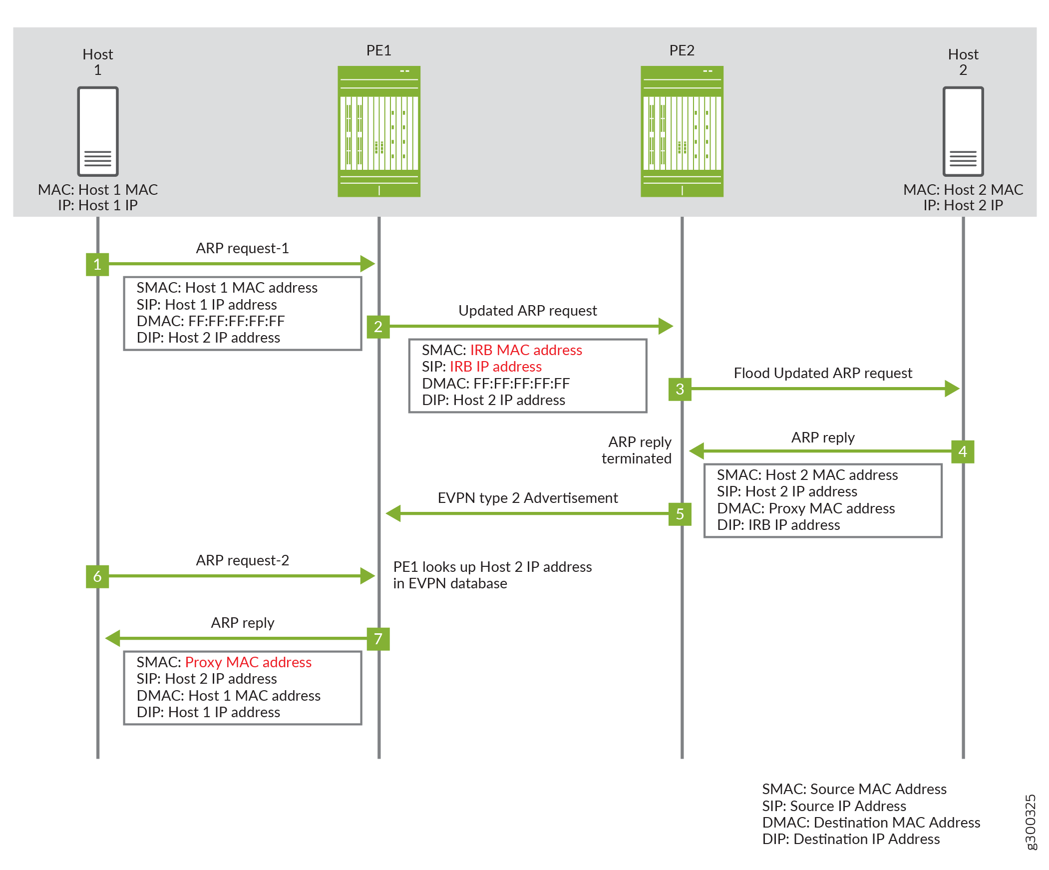
Figure 1 illustrates how proxy MAC address is applied in an edge-routed bridging EVPN network. The sequence of events for an ARP request is as follows:
-
Host 1 sends the first ARP request message to locate Host 2. The ARP request message has the MAC and IP address of host 1 as the source MAC and IP address.
-
Device PE1 receives the ARP request message. Since there are no matching entries in its MAC-IP address binding database, PE1 appropriates the ARP request message and replaces the MAC and IP address of Host 1 with the MAC and IP address of the IRB interface.
-
Device PE2 forwards the ARP request message.
-
Host 2 sends the ARP response with its MAC and IP address.
-
Device PE2 adds an entry for Host 2 to its MAC-IP address binding database and sends an EVPN type 2 advertisement message for Host 2. When PE1 receives the EVPN type 2 message, it adds an entry for Host 2 to its MAC-IP address binding database.
-
ARP request 1 times out and host 1 sends another ARP request message.
-
Device PE1 receives the second ARP request message. Since there is an entry in the MAC-IP address binding database, it responds as the ARP proxy with the proxy MAC address.
For EVPN networks with a centrally-routed bridging overlay, you assign a configured MAC address as the proxy MAC address. The configured proxy MAC address on the leaf should be the virtual gateway MAC address of the IRB on spine device or gateway. When the virtual gateway MAC address is not configured, configure the proxy MAC address to use the IRB MAC address on the centralized gateway.
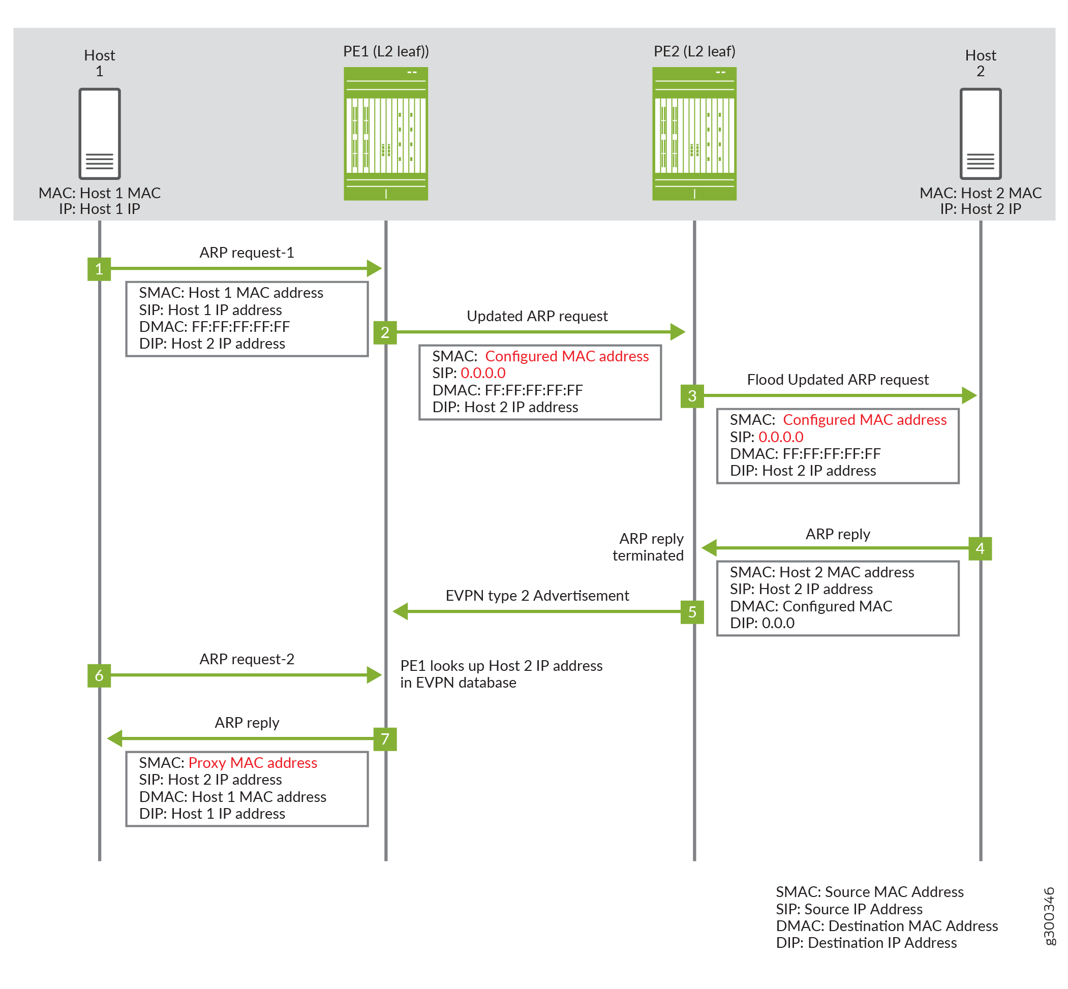
If the entry is not found in the MAC-IP address binding database in a centrally-routed bridging EVPN network, the source MAC is replaced with the configured proxy MAC and the source IP address is set to 0.0.0.0. in the ARP request. Figure 2 illustrates how proxy MAC address is applied in a centrally-routed bridging EVPN Network where Host 1 and Host 2 are connected to leaf devices PE1 and PE2 respectively. The sequence of events for the ARP request is as follows:
-
Host 1 sends the first ARP request message to locate Host 2. The ARP request message has the MAC and IP address of Host 1 as the source MAC and IP address.
-
Leaf device PE1 receives the ARP request message. Since there are no matching entries in its MAC-IP address binding database, PE1 floods the ARP request message and replaces the source MAC address of Host 1 with the configured proxy MAC address and a source IP address to 0.0.0.0.
-
Leaf device PE2 receives and forwards the ARP request message.
-
Host 2 sends the ARP response with its MAC and IP address.
-
Device PE2 adds an entry for Host 2 to its MAC-IP address binding database and sends an EVPN type 2 advertisement message for Host 2. When PE1 receives the EVPN type 2 message, it adds an entry for Host 2 to its MAC-IP address binding database.
-
ARP request 1 times out and host 1 sends another ARP request message.
-
Device PE1 receives the second ARP request message. Since there is an entry in the MAC-IP address binding database, it responds as the ARP proxy with the proxy MAC address.
This feature ensures all inter-VLAN and intra-VLAN traffic are forwarded as Layer 3 traffic to the configured gateway and that the traffic can be routed.
To enable this feature, include the proxy-mac (irb | proxy-mac-address) statement in the [edit routing-instances routing-instance-name protocols evpn] hierarchy
for the evpn instance type or in the [edit routing-instances routing-instance-name bridge-domains domain_name] hierarchy for the virtual-switch instance type.
In an EVPN network with edge-routed bridging overlay where
CE devices are directly connected to a L3 gateway device, configure proxy-mac on the gateway devices with the irb option.
In an EVPN network with a centrally-routed bridging overlay
where CE devices are connected to an L3 gateway device via layer 2
only leaf devices, configure proxy-mac on the leaf devices
with the proxy-mac-address option using the virtual or
physical gateway MAC address on the centralized L3 gateway IRB interface
as the MAC address.
The following is a sample configuration for bridge domain with support for proxy MAC for an edge-routed bridging EVPN network.
routing-instances {
    VS-1 {
        instance-type virtual-switch;
        bridge-domains {
            bd-110 {
                interface ae0.0;
                vlan-id 110;
                routing-interface irb.5;
                proxy-mac {
                     irb;
                }
	           }
        }
    }
}
Benefits of using a virtual gateway or IRB MAC address in an ARP request
With this feature, all inter-VLAN and intra-VLAN traffic for all configured routing instances will be routed to an IRB interface. This allows the following:
-
Communication between private VLANs.
-
Layer 3 security filtering at the gateway for both intra-VLAN and inter-VLAN traffic.
-
MAC address privacy. Host do not learn the MAC addresses of other hosts.