Help us improve your experience.

Let us know what you think.

Do you have time for a two-minute survey?

Announcement: Try the Ask AI chatbot for answers to your technical questions about Juniper products and solutions.

close
header-navigation
keyboard_arrow_up
close
keyboard_arrow_left
list Table of Contents

Troubleshoot SRX Series Firewalls

date_range 28-Jan-25

This chapter describes the steps to troubleshoot your SRX Series device that appears as disconnected on the Mist portal. It also discusses the packet capture (PCAP) support available for SRX Series devices deployed as WAN Edges in the Mist cloud.

Troubleshoot SRX Series Firewalls Shown as Disconnected

If the Juniper Mist™ portal shows a Juniper Networks® SRX Series Firewall as disconnected when it is online and reachable locally, you can troubleshoot the issue using the steps listed in this topic. You need console access or SSH access to the firewall to perform the troubleshooting steps.

  1. Check if the SRX Series Firewall is running on the supported Junos OS version.

    For WAN Assurance, you need Junos OS version 19.4 and later for SRX300, SRX320, SRX340, SRX345, SRX380, SRX550M, SRX1500, and SRX1600.

    You can use the show version CLI command to check the version.

  2. Check if the SRX Series Firewall has a valid IP address.

    Use the show interfaces terse command.

    content_copy zoom_out_map
    user@host >  show interfaces terse 1 match ge-0/0/0
    ge-0/0/0	  up	up		
    ge-0/0/0.0	up	up	inet	10.0.0.51/24
    
    user@host > show interfaces terse I match	irb
    irb		up	up		
    irb.0	     up	down		
    irb.2	     up	up	inet	192.168.2.1/24
    irb.8	     up	up	inet	192.168.8.1/24
    irb.10	    up	up	inet	192.168.10.1/24
    irb.24	    up	up	inet	192.168.24.1/24


    You should see the integrated routing and bridging (IRB) interface (irb.0) with an IP address. You might see multiple IRB interfaces, depending on the SRX Series model (or in the case of a chassis cluster HA configurations).

    At least one IRB interface needs to have a valid IP address. The Firewall can also connect using a management IP address, which you can see on the fxp0 interface. Ensure that either the irb or fxp0 interface has a valid IP address and has its Admin and Link states up.

  3. Ensure that the firewall can reach the gateway as shown in the following sample.
    content_copy zoom_out_map
    user@host> ping inet 10.0.0.1
    PING 10.0.0.1 (10.0.0.1): 56 data bytes
    64 bytes from 10.0.0.1: icmp_seq=0 ttl=64 time=44.967 ms
    64 bytes from 10.0.0.1: icmp_seq=l ttl=64 time=1.774 ms
    64 bytes from 10.0.0.1: icmp_seq=2 ttl=64 time=41.347 ms
    64 bytes from 10.0.0.1: icmp_seq=3 ttl=64 time=1.731 ms
    64 bytes from 10.0.0.1: icmp_seq=4 ttl=64 time=1.674 ms
    ^C
    ---10.0.0.1 ping statistics--- 	
    5 packets transmitted, 5 packets received, 0% packet loss 
    round-trip min/avg/max/stddev = 1.674/18.299/44.967/20.329 ms
    
    
  4. Check if your device can reach the Internet. Initiate a ping test toward any public server (for example, 8.8.8.8).
    content_copy zoom_out_map
    user@host> ping inet 8.8.8.8 
    PING 8.8.8.8 (8.8.8.8): 56 data bytes
    64 bytes from 8.8.8.8: icmp_seq=0 ttl=58 time=9.789 ms
    64 bytes from 8.8.8.8: icmp_seq=1 ttl=58 time=5.206 ms
    64 bytes from 8.8.8.8: icmp_seq=2 ttl=58 time=4.679 ms
    64 bytes from 8.8.8.8: icmp_seq=3 ttl=58 time=4.362 ms
    64 bytes from 8.8.8.8: icmp_seq=4 ttl=58 time=4.497 ms
    ^C
    --- 8.8.8.8 ping statistics ---
    5 packets transmitted, 5 packets received, 0% packet loss
    round-trip min/avg/max/stddev = 4.362/5.707/9.789/2.061 ms
  5. Check if the firewall can resolve oc-term.mistsys.net.
    content_copy zoom_out_map
    user@host> ping oc-term.mistsys.net 
    PING ab847c3d0fcd311e9b3ae02d80612151-659eb20beaaa3ea3.elb.us-west-1.amazonaws.com (13.56.90.212): 56 data bytes

    If the firewall is not resolving oc-term.mistsys.net, make sure that the firewall has a DNS server configured.

    content_copy zoom_out_map
    user@host> show configuration | display set | grep name-server 
    set system name-server 8.8.8.8
    set system name-server 8.8.4.4
    If the firewall doesn't have a DNS server, configure the server as shown in the following example:
    content_copy zoom_out_map
    user@host# set system name-server 8.8.8.8
  6. Ensure firewall ports are open (for example: tcp port 2200 for oc-term.mistsys.net).

    See the following table to determine which port to enable, depending on your cloud environment:

    Table 1: Ports to Enable in Different Juniper Mist Clouds
    Service Type Global 01 Global 02 Europe 01
    SRX Series redirect.juniper.net (TCP 443) redirect.juniper.net (TCP 443) redirect.juniper.net (TCP 443)
    ztp.mist.com (TCP 443) ztp.gc1.mist.com (TCP 443) ztp.eu.mist.com (TCP 443)
    oc-term.mistsys.net (TCP 2200) oc-term.gc1.mist.com (TCP 2200) oc-term.eu.mist.com (TCP 2200)

    You can check the connections using the following command:

    content_copy zoom_out_map
    user@host> show system connections | grep 2200 
    tcp4      0      0      10.0.0.51.49981   54.83.93.93.2200    ESTABLISHED
  7. Check the system time on the firewall to make sure the time is correct.
    content_copy zoom_out_map
    user@host> show system uptime 
    Current time: 2021-08-23 19:39:17 UTC
    Time Source: LOCAL CLOCK 
    System booted: 2021-07-14 22:40:20 UTC (5w4d 20:58 ago)
    Protocols started: 2021-07-14 22:45:39 UTC (5w4d 20:53 ago)
    Last configured: 2021-08-23 19:34:05 UTC (00:05:12 ago) by root
    7:39PM up 39 days, 20:59, 2 users, load averages: 0.66, 1.07, 0.92

    If the system time is not correct, configure it. For more information, see Configure Date and Time Locally.

  8. Check device-id to make sure it is in the format <org_id>.<mac_addr>, as shown below:
    content_copy zoom_out_map
    user@host# show system services outbound-ssh 
    traceoptions {
       file outbound-ssh.log size 64k files 5;
       flag all;
    }
    client mist {
       device-id abcd123445-1234-12xx-x1y2-ab1234xyz123.<mac>;
       secret "$abc123"; ## SECRET-DATA
       keep-alive {
          retry 12;
          timeout 5;
       }
       services netconf;
       oc-term-staging.mistsys.net {
          port 2200;
          retry 1000;
          timeout 60;
       }
    }

    See outbound-ssh for more information.

    You can also examine the log messages by using the command show log messages.

  9. Deactivate and then reactivate the outbound SSH, as shown below:
    • To deactivate:
      content_copy zoom_out_map
      user@host# deactivate system services outbound-ssh client mist
      user@host# commit
    • To activate again:
      content_copy zoom_out_map
      user@host# activate system services outbound-ssh client mist
      user@host# commit
  10. If you are adding the SRX Series Firewall for the first time, do the following:
    • Delete the present Juniper Mist configuration from the firewall using the delete command.
    • Onboard the firewall again. For details on getting your SRX Series Firewall up and running in the Mist cloud, see Cloud-Ready SRX Firewalls .
    • Verify system service outbound-ssh and system connections using the following commands:
      • show system services outbound-ssh
      • show system connections | grep 2200

Troubleshoot SRX Series Firewalls Using Packet Captures

SRX Series Firewalls support manual packet captures (PCAP). Packet capture is a tool that helps you to analyze network traffic and troubleshoot network problems. It captures real-time data packets traveling over the network for monitoring and logging.

Note:

SRX Series Firewalls do not support dynamic packet capture.

Manual packet captures are initiated by users from the WAN Edge Packet capture page.

To initiate manual PCAP for an SRX Series Firewall:

  1. Go to Site > WAN Edge Packet Captures.

  2. On the WAN tab, click Add WAN Edge + and select an SRX Series Firewall.

    Figure 1: WAN Edge Packet Capture WAN Edge Packet Capture
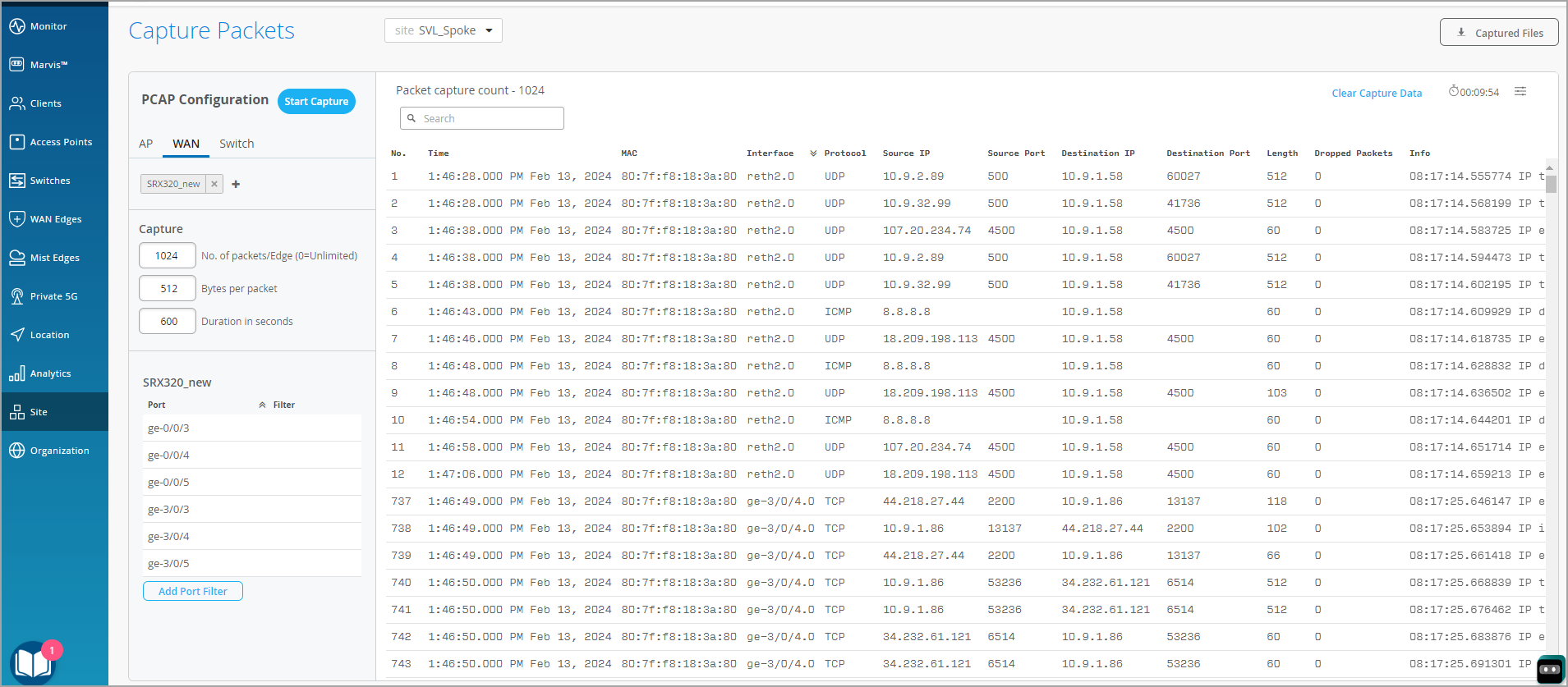
  3. Specify the number of packets captured, packet size in bytes, and the duration of the capture session.

  4. Use the Add Port Filter option to specify the port. In this pane, you can also enter filters in the TCPDUMP Expression text box.
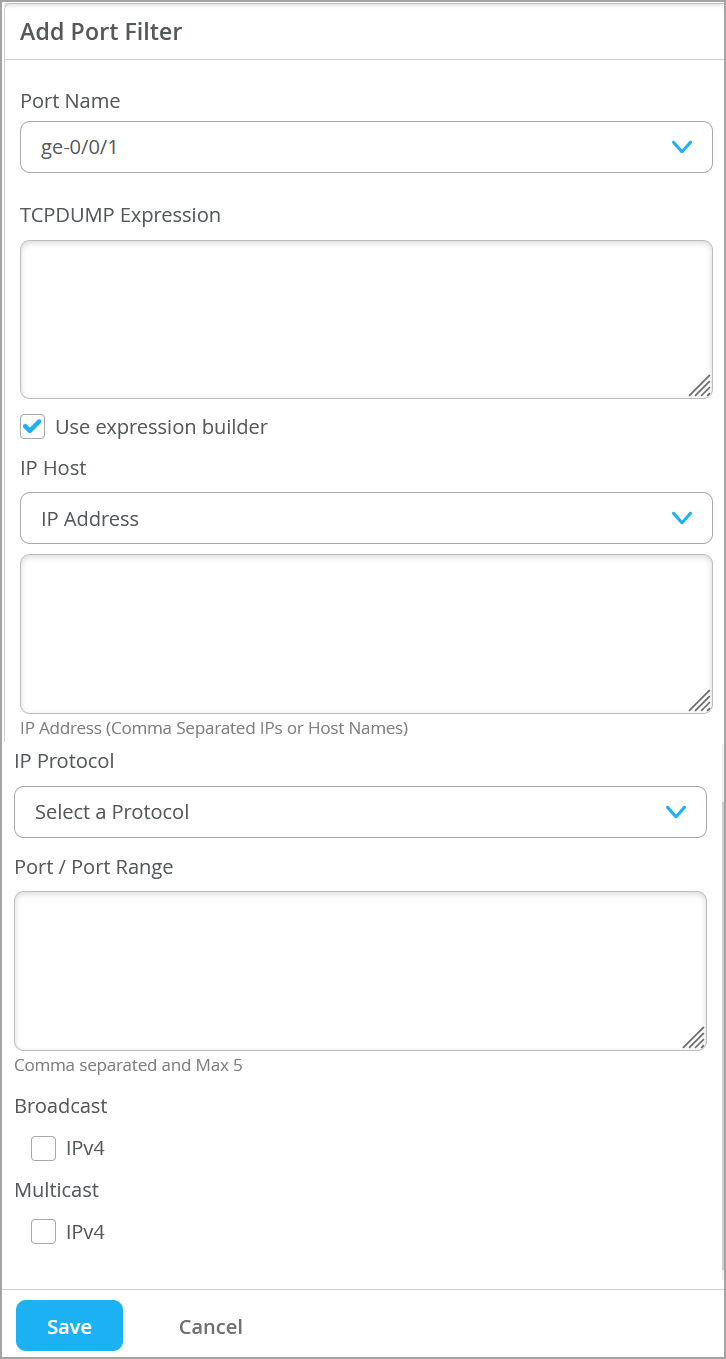
  5. Optionally, select Use Expression builder to build the expression for packet capture. Expression builder is an interactive GUI tool to build custom filters in tcpdump syntax for use in the capture session. You can let the builder start the filter entry and then add to or delete from the entry manually. You can specify the following options:
    • IP host
    • Protocols
    • Port and port ranges
    • IP broadcast
    • IP multicast

    When you enter addresses and protocols into the expression builder, the portal automatically generates the tcpdump expression on the page. You can edit the expression if needed.

  6. Click Start Capture. The packet capture content is streamed on the page.

  7. You can download the file for offline analysis by clicking Captured Files on the top right side of the page.

See also: Dynamic and Manual Packet Captures.

file_download PDF
{ "lLangCode": "en", "lName": "English", "lCountryCode": "us", "transcode": "en_US" }
English
keyboard_arrow_right
footer-navigation
keyboard_arrow_down
file_download
{ "lLangCode": "en", "lName": "English", "lCountryCode": "us", "transcode": "en_US" }
language