- play_arrow Overview
- play_arrow Platform Considerations
- play_arrow WAN Configuration for Session Smart Routers
- WAN Assurance Configuration Overview
- Configure Sites and Variables for Session Smart Routers
- Configure Networks for Session Smart Routers
- Configure Applications for Session Smart Routers
- Configure Application Policies on Session Smart Routers
- Configure Hub Profile for Session Smart Routers
- Configure Path Selection from Hub-to-Spoke with Traffic Steering
- Configure WAN Edge Templates for Session Smart Routers
- Routing Configuration on Session Smart Routers
- Onboard Session Smart Routers for WAN Configuration
- Onboard Session Smart Routers with Static IP Address
- IDP-Based Threat Detection on Session Smart Routers
- Upgrade a WAN Edge Session Smart Router
- Configure VRF Route Leaking for Session Smart Routers
- Revoke DHCP Lease on a WAN Edge Device
- Reserve DHCP IP Address
- play_arrow WAN Configuration for SRX Series Firewalls
- WAN Assurance Configuration Overview
- Configure Sites and Variables for SRX Series Firewalls
- Configure Applications for SRX Series Firewalls
- Configure Networks for SRX Series Firewalls
- Configure Application Policies on SRX Series Firewalls
- Configure Hub Profiles for SRX Series Firewalls
- Configure WAN Edge Templates for SRX Series Firewalls
- Routing Configuration on SRX Series Firewalls
- Onboard SRX Series Firewalls for WAN Configuration
- IDP-Based Threat Detection for SRX Series Firewalls
- Enable Application Visibility on SRX Series Firewalls
- Monitor the Service Status of SRX Series Firewalls
- Upgrade a WAN Edge SRX Series Firewalls
- Configure a Custom VR for SRX Series Firewalls
- Revoke DHCP Lease on a WAN Edge Device
- Reserve DHCP IP Address
- play_arrow Secure Edge Connector
- play_arrow Cellular Edges
- play_arrow Monitor and Troubleshoot
- WAN Assurance Monitoring, SLE, and Troubleshooting Overview
- Monitor SRX Series Firewall Deployed as WAN Edge
- Monitor Session Smart Router Deployed as WAN Edge
- Service-Level Experiences for Session Smart Router Deployed as WAN Edge
- Troubleshoot Session Smart Router Deployed as WAN Edge
- Speed Tests for Session Smart Router Deployed as a WAN Edge (BETA)
- Dynamic and Manual Packet Captures
- Troubleshoot SRX Series Firewalls
- Replace a WAN Edge Device
- WAN Edge Testing Tools
Full Stack Design for Session Smart Routers
The Juniper® SD-WAN driven by Mist AI™ Full Stack design example is a follow-up to the Session Smart™ Router Mist WAN Assurance deployment documentation found in the Juniper Mist WAN Configuration Guide.
Overview
With this example you’re expanding network capabilities by integrating Mist APs and Juniper EX Switches. This is more than just WAN Assurance, it’s the Juniper AI Driven Enterprise. This full stack guide shows you how to set up your Juniper SD-WAN Session Smart WAN edge devices in concert with Mist wireless Access Points (APs) deployed in Wireless Assurance, and Juniper EX Series Switches deployed in Wired Assurance. This brings all your network devices into a cohesive onboarding, monitoring, and troubleshooting dashboard.
The Session Smart Full Stack Guide begins at the highest level of WAN Assurance, focusing on a key component known as the Session Smart Router. After completing the Juniper Validated Design (JVD) topology found in the Juniper Mist WAN Configuration Guide, you should already have this WAN Edge device deployed in a hub and spoke network. The Session Smart Router serves as the WAN edge device and foundation for building out your entire network. We'll evaluate and test the complete end-to-end solution to further optimize your network. This test encompasses the entire technology stack and is specifically designed for a branch that utilizes Juniper equipment.
For successful implementation of this guide, you'll need at least one Juniper EX Switch to onboard into the Mist cloud. If you plan to do advanced testing with virtual circuits, two EX Switches is ideal. Additionally, you can incorporate a Mist AP into the setup to enhance the wireless capabilities of the network. Onboarding those into your LAN network for Mist management gives admins the Juniper AI Driven Enterprise to monitor and manage their WAN edge, switches, and APs all in the Mist dashboard.
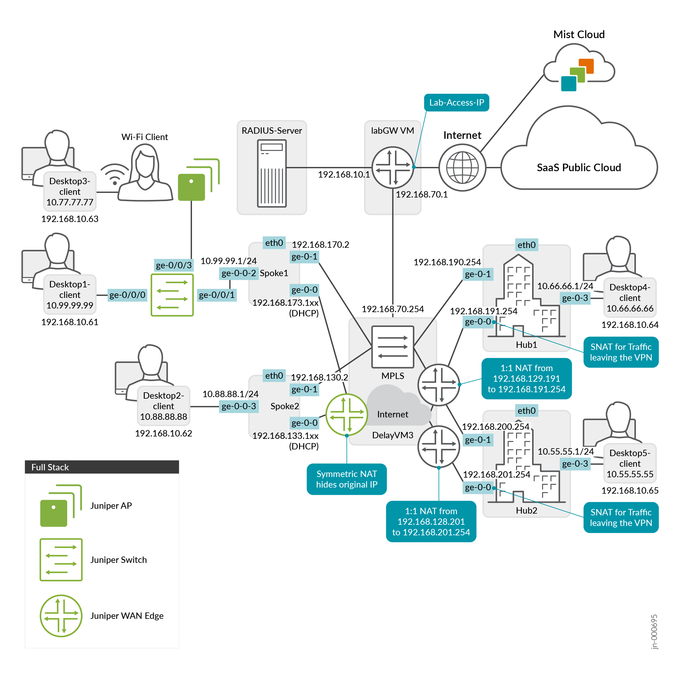
Figure 1 shows the Full Stack Juniper Mist WAN Assurance topology used in this example.
Requirements
To get started, you’ll need to alter some of the interfaces found in the Juniper Mist WAN Configuration Guide topology. We’ll show you how to do this using a Spokes configuration template found in the Mist WAN Configuration Guide. See Configure WAN Edge Templates for Session Smart Routers.
- Desktop3 VM (VLAN1077) is re-used and no longer attached to Spoke3. Desktop3 VM is now a viewer for the Raspberry Pi, the Wireless Client. Alternatively, you could use a local notebook.
- Desktop1 VM (VLAN1099) is no longer directly attached to Spoke1 and needs to be re-attached to the interface ge-0/0/0 of the new branch switch.
Create a New Spokes Configuration Template
To create a new spokes configuration quickly and efficiently, you can clone the template for an existing spoke and then make the necessary changes. It makes things much easier.
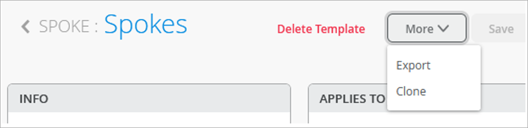
- Click More and select
Clone. Figure 2: Selecting Clone Option for Template
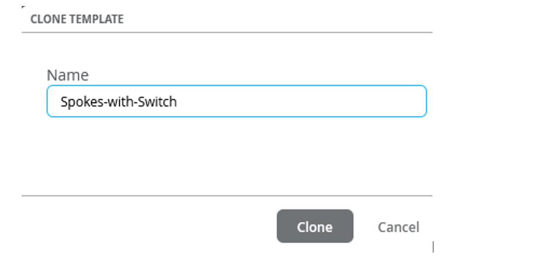
- Enter the name as Spokes-with-Switch and click
Clone. Figure 3: Saving Cloned Template
 Tip:
Tip:Refresh your browser after cloning. This ensures objects displayed are truly refreshed.
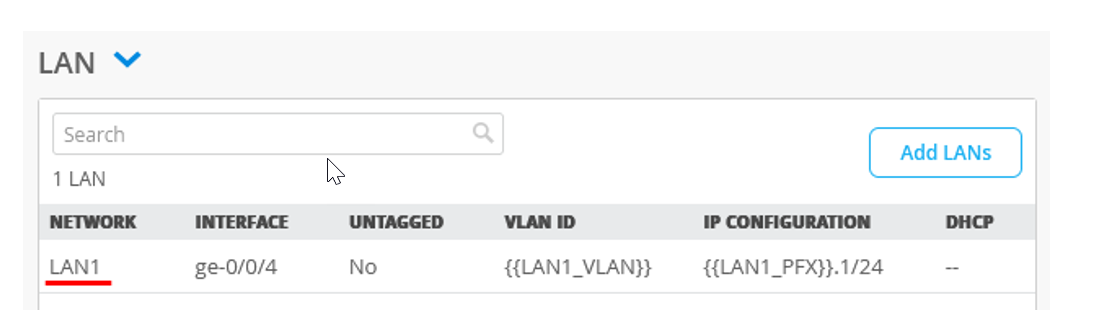
Edit the LAN Interface
- On the LAN interface configuration section, edit the existing interface
(LAN1). Figure 4: LAN Interface Configuration
 Change the name of LAN interface as SPOKE-LAN1 and set the Interface to ge-0/0/2.Figure 5: Modify LAN Interface Configuration
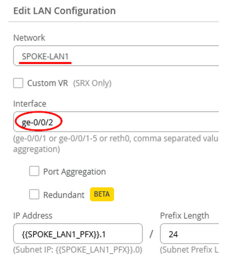
- Continue to configure the SPOKE-LAN1 LAN interface: Figure 6: Modify LAN Interface Configuration
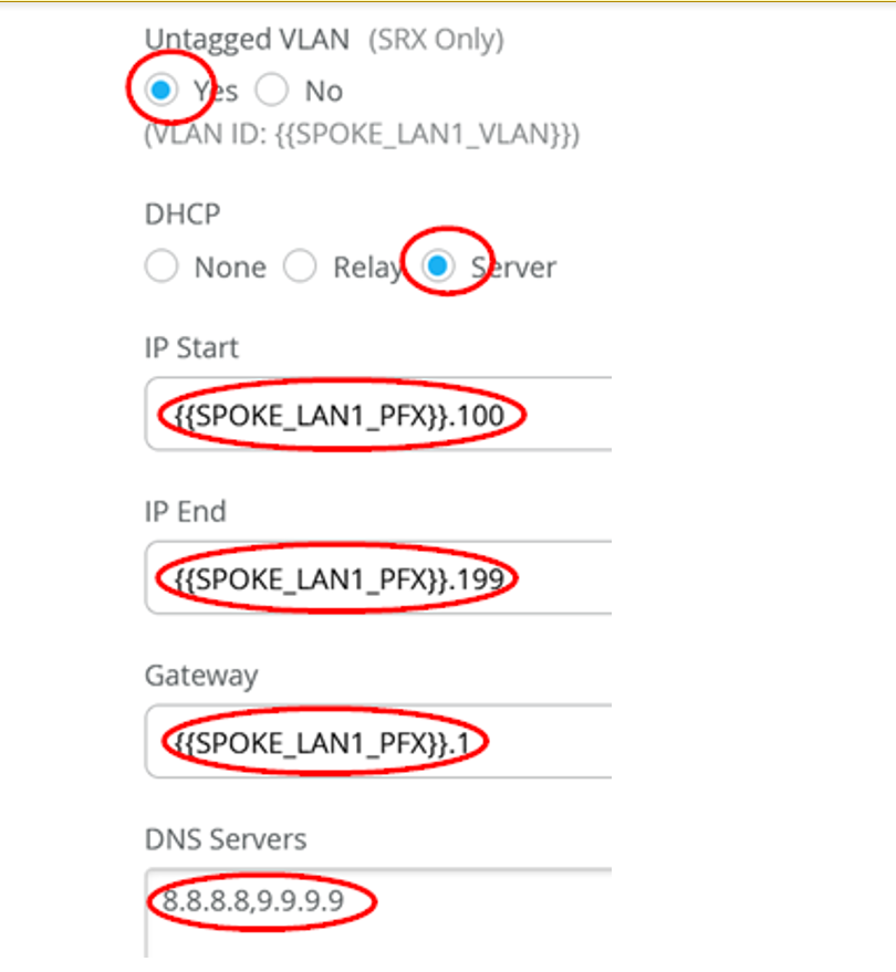
DHCP: Server
IP Start: {{SPOKE_LAN1_PFX}}.100
IP End: {{SPOKE_LAN1_PFX}}.199
Gateway: {{SPOKE_LAN1_PFX}}.1
DNS Servers: 8.8.8.8, 9.9.9.9
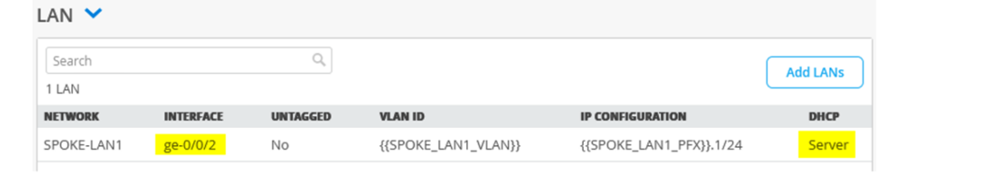
- Figure 7shows the LAN
interface you modified. Figure 7: Summary of LAN Interface
Assign the New Template to a Site
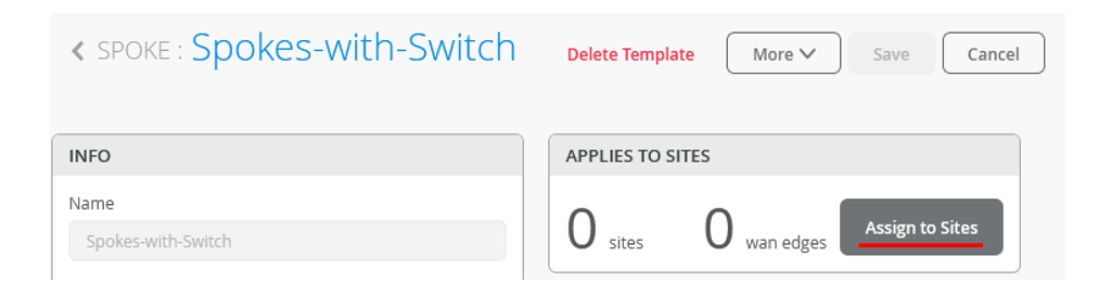
- Scroll to the top of the WAN Edge Templates page and click
Assign to Sites under Spokes panel. Figure 8: Assign Spoke Templates to Sites
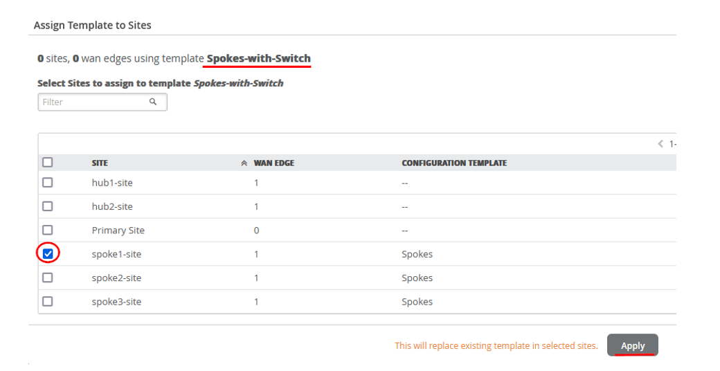
- In the Assign Template to Sites pane, select spoke1-site template
and click Apply. Figure 9: Select Sites to Assign Spoke Templates
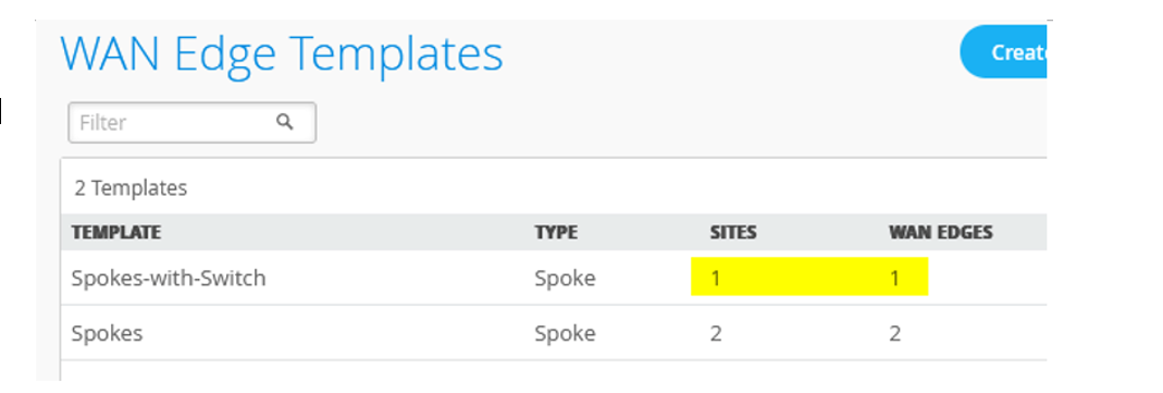
- Review the Template Settings as shown in Figure 10. Figure 10: Details of WAN Edge Template
Change Spoke Variables in Preparation for Onboarding
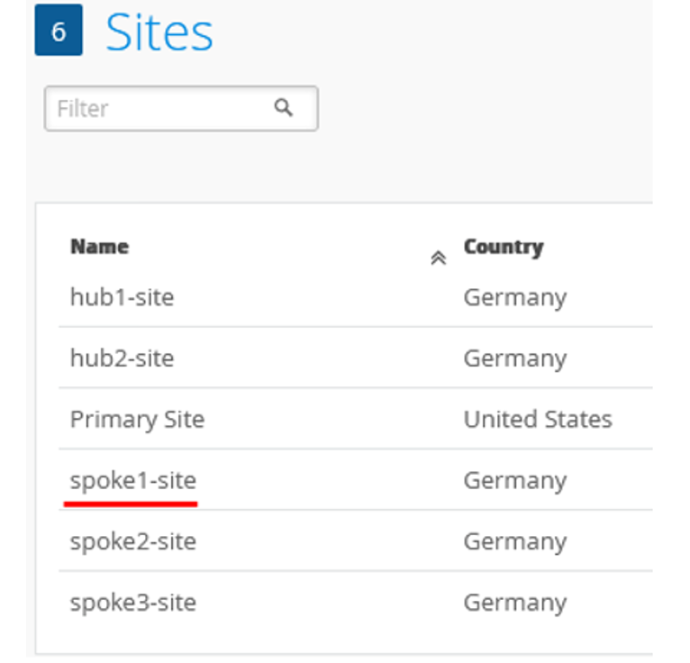
- Click on the site spoke1-site. This is the same
site, to which you have applied the template in previous procedure. Figure 11: Selecting Sites for Modifying
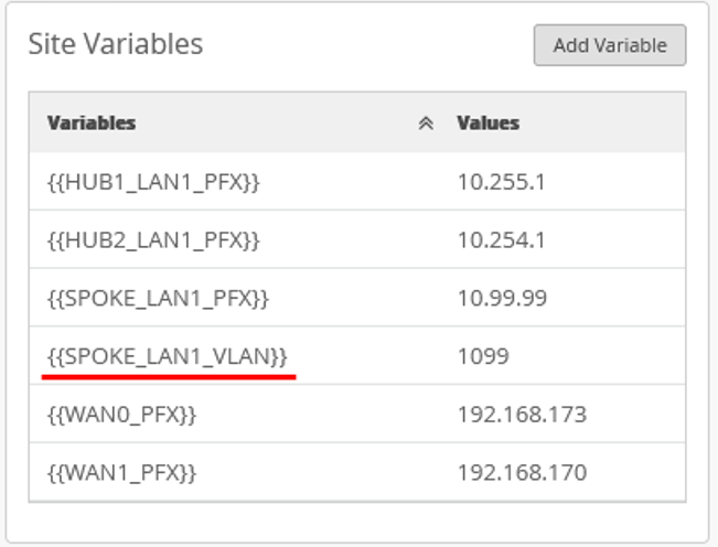
- Scroll down the screen to the Site Variables
settings pane and select the variable {{SPOKE_LAN1_VLAN}}. Figure 12: Site Variables
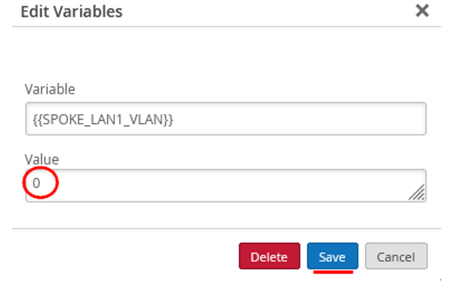
- Change the Value to 0 as you do not need a tagged
VLAN, and then click Save. Figure 13: Modify Site Variables
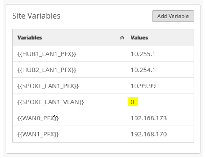
- Review your changes in the Site Variable pane. Figure 14: Site Variables
Add Your Switch to the Topology
Now it is time to onboard your switch and add it to your infrastructure. For details on how to onboard your switch, refer to the product documentation for your switch in the Juniper TechLibrary.
For details on getting a new cloud-ready EX switch up and running in the Juniper Mist AI cloud portal, see Cloud-Ready EX and QFX Switches with Mist.
To assign a switch to a site:
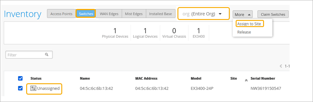
- In the Inventory page, ensure the inventory view is set to org
(Entire Org) and refresh your browser until you see all
your devices. Figure 15: EX Series Switch in Inventory
- In the Assign Switches page:
- Select the spoke1-site.
- Disable Manage configuration with Mist option. You can enable this option at a later stage if required.
Figure 16: Selecting Site for Assigning Switch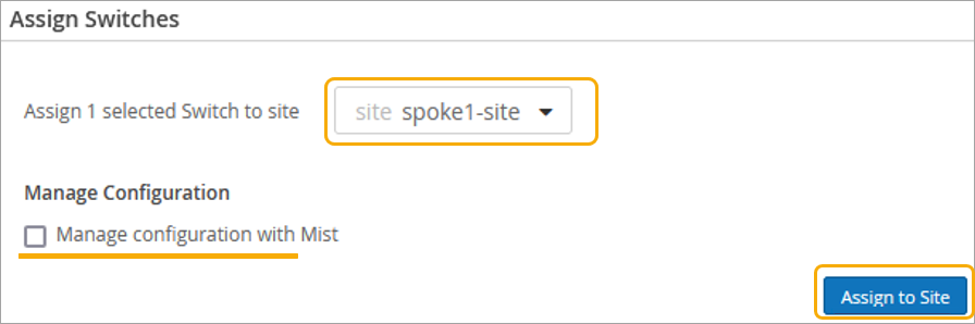
- Confirm the changes in the inventory once you assign the device to the
site.
You can see spoke1-site under New Site.
Figure 17: Assigned Switch to Site Details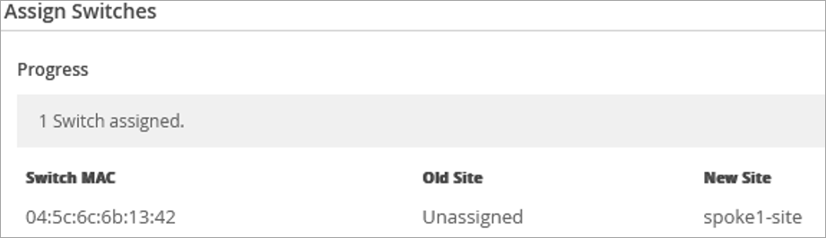
- In the Juniper Mist portal, go to Switches and
select spoke1-site. Figure 18: Selecting Assigned Switch for Modification
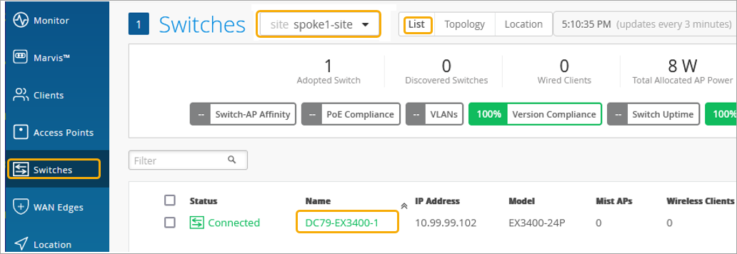 The page displays the list of switches assigned to the site.
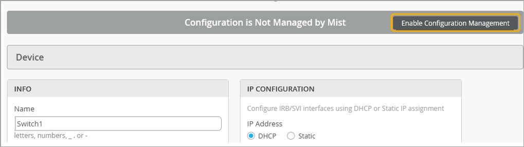
 - Verify the device name, then scroll down to Switch
Configuration section and check Enable
Configuration Management. Figure 19: Configuration of Assigned Switch
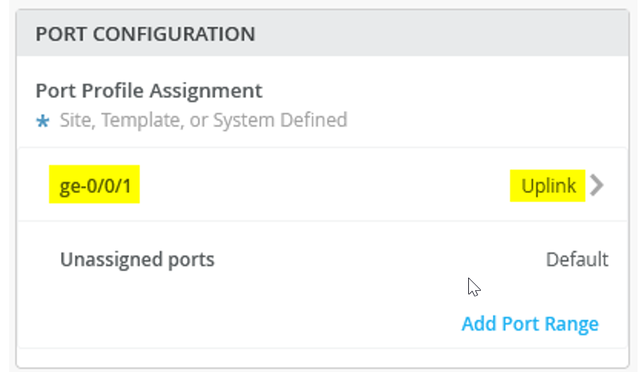
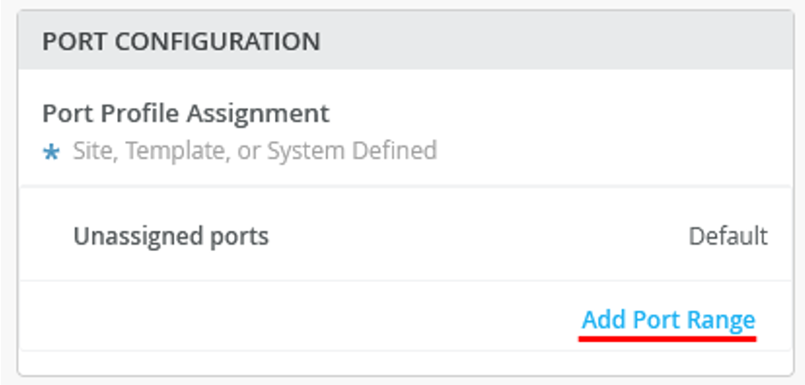
- Under Port Configuration, click Add Port
Range. Figure 20: Port Configuration of Assigned Switch
- In the New Port Range page, configure the following options:
Set the Port IDs as ge-0/0/1.
Select the existing Configuration Profile as Uplink.
Figure 21: Port Configuration of Assigned Switch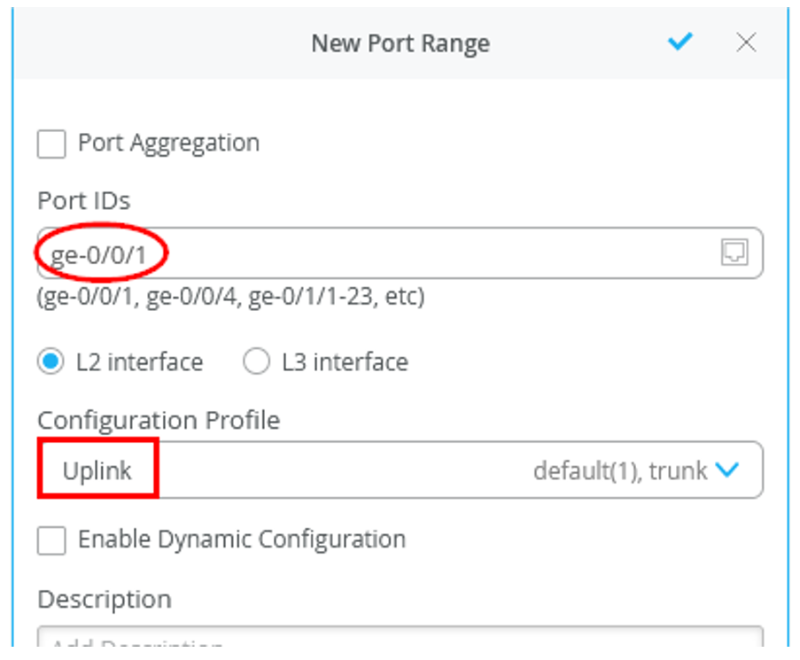
- Figure 20 shows the
summary of port configuration. Figure 22: Port Configuration of Assigned Switch