- play_arrow Getting Started
- play_arrow Blueprints
- play_arrow Blueprint Analytics
- What are Blueprint Analytics
- play_arrow Dashboards
- What are Blueprint Analytics Dashboards
- Configure Auto-Enabled Blueprint Analytics Dashboards
- Instantiate Predefined Blueprint Analytics Dashboard
- Create Blueprint Analytics Dashboard
- Export Blueprint Analytics Dashboard
- Import Blueprint Analytics Dashboard
- Update Blueprint Analytics Dashboard
- Delete Blueprint Analytics Dashboard
- play_arrow Anomalies
- play_arrow Probes
- play_arrow Predefined Reports
- play_arrow Root Causes
- play_arrow Staged Datacenter Blueprints
- play_arrow Physical
- play_arrow Build
- play_arrow Topology
- play_arrow Nodes
- Nodes (Datacenter)
- Create Access Switch
- Delete Node
- Update Deploy Mode (Datacenter)
- Unassign Device (Datacenter)
- Execute CLI Show Command (Data Center Blueprint)
- play_arrow Change Hostnames / Names
- Change Assigned Interface Map
- Change Assigned ASN (Datacenter)
- Change Assigned Loopback IP Address (Datacenter)
- Edit Device Properties (Datacenter)
- Update Port Channel ID Range
- View Node's Static Routes
- Update Tags on Node (Datacenter)
- play_arrow Generic Systems (Internal/External)
- play_arrow Links
- Links (Datacenter)
- play_arrow Add Links
- play_arrow Cabling Map
- play_arrow Link Speeds
- play_arrow LAG
- Update Tags on Link (Datacenter)
- Change Assigned Link IP Addresses (Datacenter)
- Update Link Properties
- Fetch LLDP Data (Datacenter)
- Delete Link (Datacenter)
- play_arrow Interfaces
- play_arrow Racks
- play_arrow Pods
- play_arrow Planes
-
- play_arrow Virtual
- play_arrow Virtual Networks
- What are Virtual Networks
- Create Virtual Network
- Update Virtual Network Resource Assignments
- Reset Virtual Network Resource Group Override
- Import Virtual Network
- Export Virtual Network to CSV File
- Update Virtual Network Assignments
- Move Virtual Network to Different Routing Zone
- Update Virtual Network Tags
- Change Virtual Network Description
- Change Virtual Network Details
- Delete Virtual Network
- play_arrow Routing Zones
- play_arrow Static Routes
- play_arrow Protocol Sessions
- play_arrow Virtual Infrastructure
-
- play_arrow Policies
- play_arrow Endpoints
- play_arrow Security Policies
- play_arrow Interface Policies
- play_arrow Routing Policies
- play_arrow Routing Zone Constraints
- play_arrow Tenants
-
- play_arrow Data Center Interconnect (DCI)
- play_arrow Integrated Interconnect
- play_arrow Over the Top or External Gateways
- play_arrow Settings
- Update ESI MAC msb
-
- play_arrow Catalog
- play_arrow Logical Devices
- play_arrow Interface Maps
- play_arrow Property Sets
- play_arrow Configlets
- play_arrow AAA Servers
- play_arrow Tags
-
- play_arrow Tasks
- play_arrow Connectivity Templates
- Connectivity Templates Introduction
- play_arrow Primitives
- Primitive: Virtual Network (Single)
- Primitive: Virtual Network (Multiple)
- Primitive: IP Link
- Primitive: Static Route
- Primitive: Custom Static Route
- Primitive: BGP Peering (IP Endpoint)
- Primitive: BGP Peering (Generic System)
- Primitive: Dynamic BGP Peering
- Primitive: Routing Policy
- Primitive: Routing Zone Constraint
- User-defined
- Pre-defined
- Create Connectivity Template for Multiple VNs on Same Interface (Example)
- Create Connectivity Template for Layer 2 Connected External Router (Example)
- Update Connectivity Template Assignments
- Add / Remove Tags on Connectivity Template
- Update Connectivity Template
- Delete Connectivity Template
- play_arrow Fabric Settings
- play_arrow Fabric Policy
- play_arrow Severity Preferences
-
-
- play_arrow Staged Freeform Blueprints
- Freeform Introduction
- play_arrow Blueprints
- play_arrow Physical
- play_arrow Selection
- play_arrow Topology
- play_arrow Systems
- Systems Introduction (Freeform)
- Create Internal System (Freeform)
- Create External System (Freeform)
- Update Assigned Config Template(Freeform)
- Update System Name (Freeform)
- Update Hostname (Freeform)
- Change Assigned Device Profile (Freeform)
- Update System ID Assignment (Freeform)
- Update Deploy Mode (Freeform)
- Add / Remove Tags on System (Freeform)
- Delete System (Freeform)
- Device Context (Freeform)
- play_arrow Links
-
- play_arrow Resource Management
- Resource Management Introduction (Freeform)
- play_arrow Blueprint Resources
- play_arrow Allocation Groups
- play_arrow Local Pools
- play_arrow Catalog (Freeform)
- play_arrow Config Templates
- play_arrow Device Profiles
- play_arrow Property Sets
- play_arrow Tags
-
- play_arrow Tasks
- play_arrow Uncommitted Blueprints
- play_arrow Active Datacenter Blueprints
- play_arrow Time Voyager (Blueprints)
- play_arrow Devices
- Device Configuration Lifecycle
- What are Managed Devices
- Add Managed Device
- Drain Device Traffic
- Upgrade Device NOS
- Device AAA
- play_arrow Device
- play_arrow Agent
- play_arrow Pristine Config
- play_arrow Telemetry
- play_arrow Apstra ZTP
- What is Apstra ZTP
- Create User Profile for Communicating with ZTP Server
- Download and Deploy Apstra ZTP Server VM
- Configure Static Management IP Address for Apstra ZTP Server
- Replace SSL Certificate for Apstra ZTP Server GUI
- Create Vendor-specific Custom Configuration
- Configure Credentials for Apstra ZTP Server GUI
- Configure Apstra Server Connection Details
- Configure DHCP Server for Apstra ZTP
- ztp.json Keys
- Configure ztp.json with Configurator
- Configure ztp.json with CLI
- Show Apstra ZTP Logs
- Onboard Devices with Apstra ZTP
- Check ZTP Status of Devices and Services
- Reset Apstra ZTP GUI Admin Password
- Authenticate User (AZTP REST API)
- play_arrow Device Profiles
- play_arrow Design
- play_arrow Logical Devices
- play_arrow Interface Maps
- play_arrow Rack Types
- play_arrow Templates
- play_arrow Config Templates (Freeform)
- play_arrow Configlets (Datacenter)
- play_arrow Property Sets (Datacenter)
- play_arrow TCP/UDP Ports
- play_arrow Tags
-
- play_arrow Resources
- play_arrow Analytics - Telemetry
- play_arrow Analytics - Flow
- play_arrow Apstra Flow Overview
- play_arrow Dashboards
- play_arrow Supported Flow Records
- play_arrow Flow Enrichment
- play_arrow Monitor Apstra Flow
- play_arrow Configuration Reference
- play_arrow API
- play_arrow Additional Documentation
- play_arrow Knowledge Base
-
- play_arrow Analytics - Exploratory Analytics
- play_arrow External Systems (RBAC Providers)
- play_arrow Providers
- play_arrow Provider Role Mapping
-
- play_arrow Platform
- play_arrow User Management
- play_arrow Security
- play_arrow External Services
- play_arrow Streaming
- Event Log (Audit Log)
- Licenses
- play_arrow Apstra VM Clusters
- play_arrow Developers
- play_arrow Technical Support
- Check Apstra Versions and Patent Numbers
-
- play_arrow Favorites & User
- play_arrow Apstra Server Management
- Apstra Server Introduction
- Monitor Apstra Server via CLI
- Restart Apstra Server
- Reset Apstra Server VM Password
- Reinstall Apstra Server
- Apstra Database Overview
- Back up Apstra Database
- Restore Apstra Database
- Reset Apstra Database
- Migrate Apstra Database
- Replace SSL Certificate on Apstra Server with Signed One
- Replace SSL Certificate on Apstra Server with Self-Signed One
- Change Apstra Server Hostname
- FIPS 140-2 Support
- play_arrow Apstra CLI Utility
- play_arrow Guides
Hypervisor and Fabric VLAN Config Mismatch Probe
Hypervisor & Fabric VLAN Config Mismatch Probe Overview
Purpose | Calculate VLAN mismatch between configured virtual networks on leaf devices and VLANs needed by VMs running on hypervisors attached to leaf devices. (Formerly known as Virtual Infra VLAN Match). Detects misconfiguration of hypervisor trunk logical switches when VLAN tag is configured inside a VM (not on the bridge itself). | ||||||||||||||||
Source Processors |
| ||||||||||||||||
Additional Processor(s) |
|
Usage with NSX-T Integration
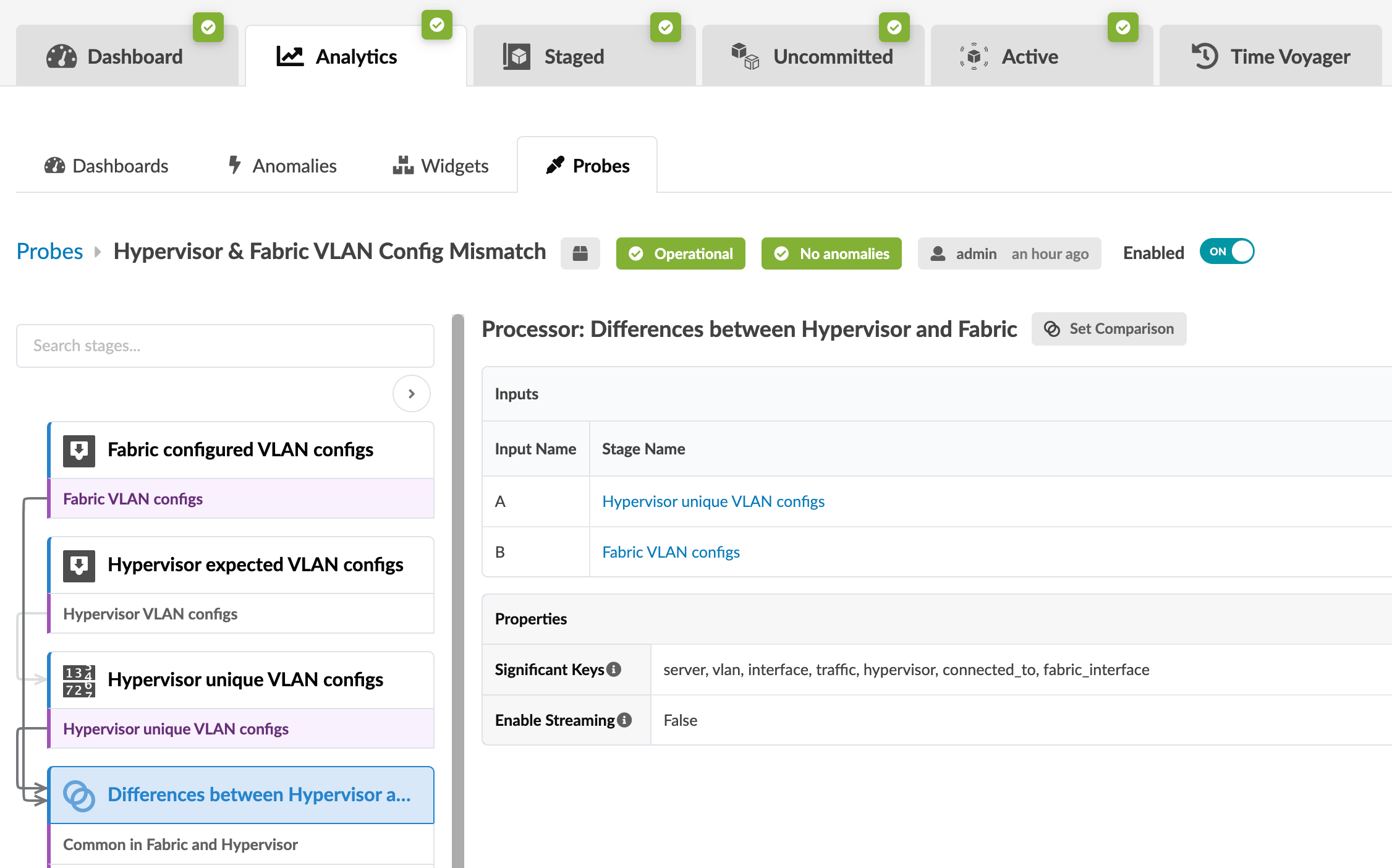
- From the blueprint, navigate to Analytics > Probes
and click Hypervisor & Fabric VLAN Config Mismatch in
the probe name list to go to its details. When the VLANs between the data center
fabric and the NSX-T transport nodes match, then the probe looks similar to the
image below:
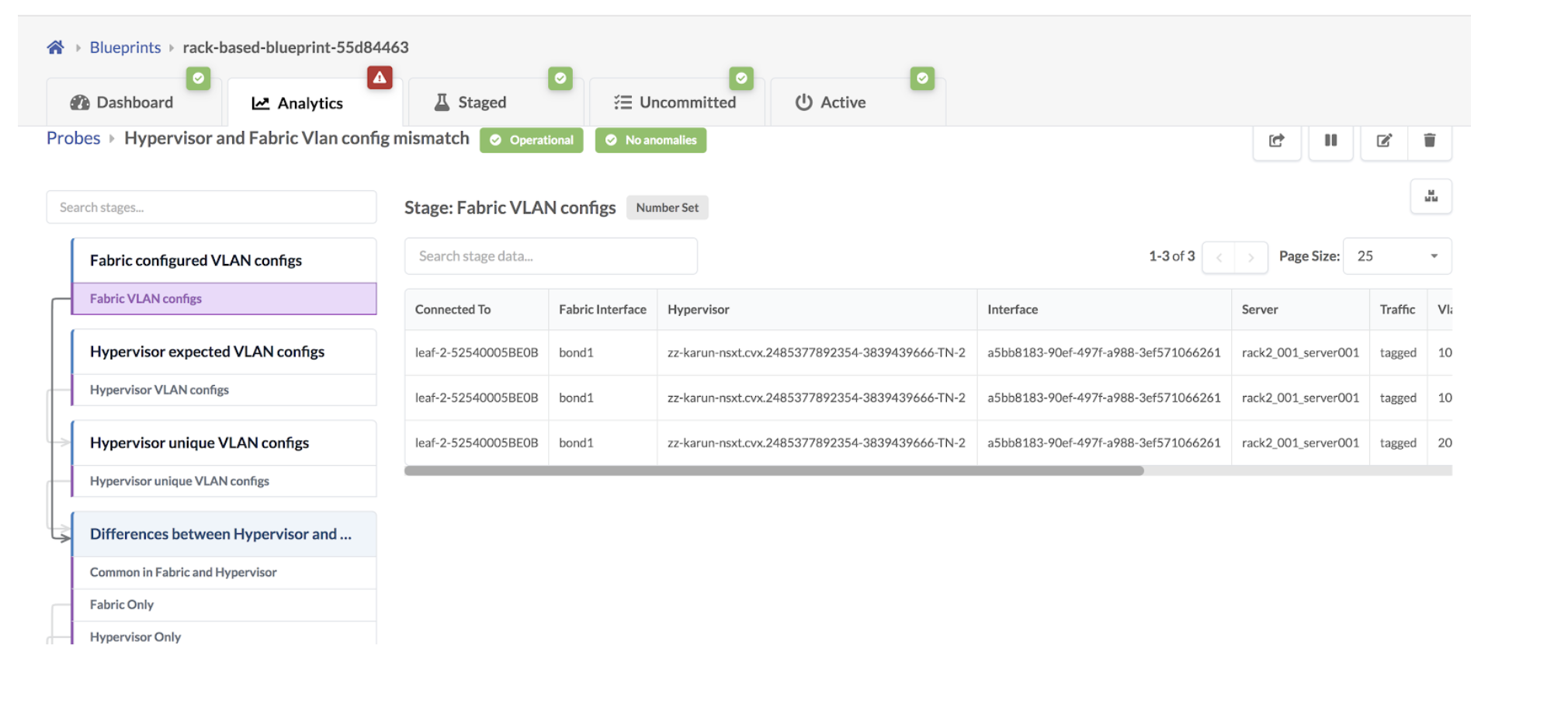
- Click the Fabric VLAN Configs stage to show the VLANs
tagged towards NSX-T transport nodes on fabric ToR leaf devices as shown below:
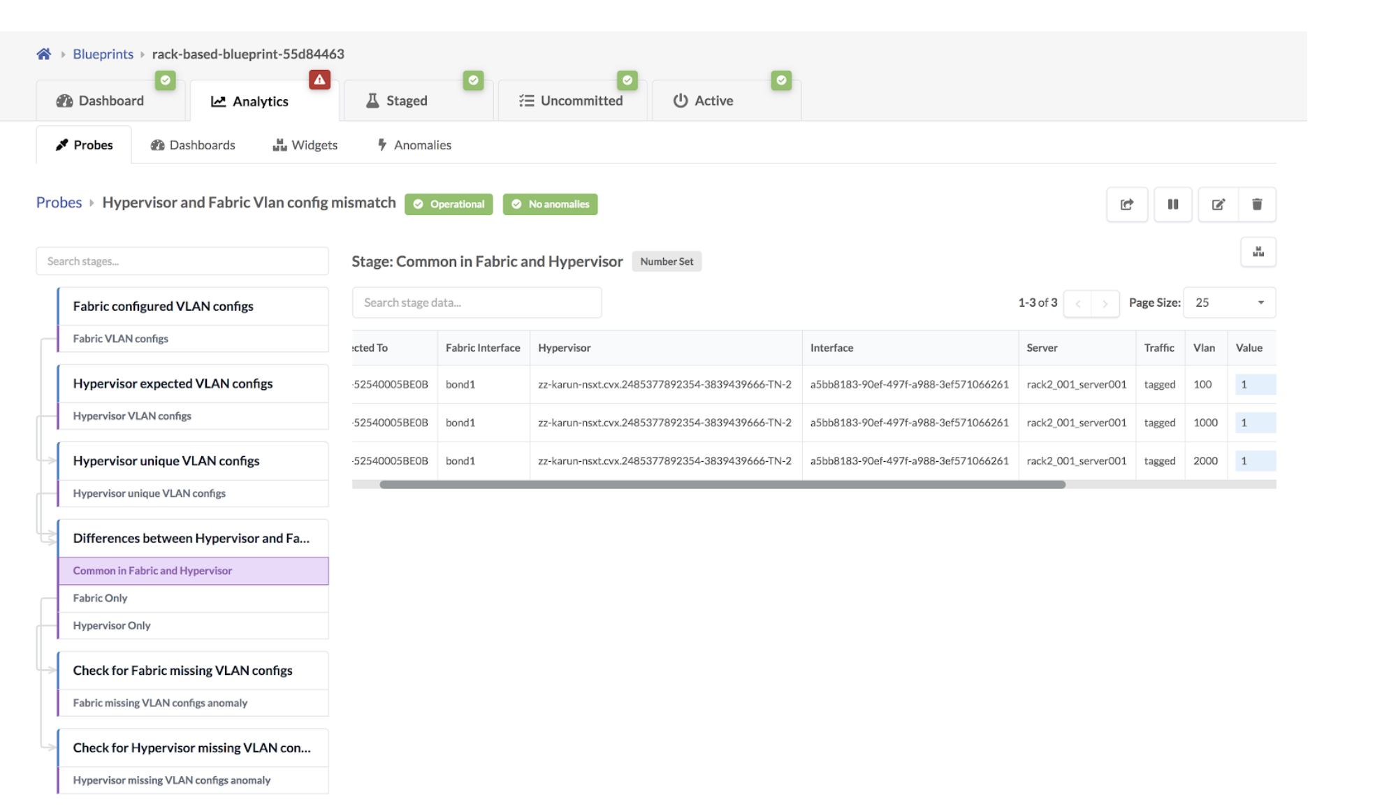
- Click the Common in Fabric and Hypervisor stage to show
that VLANs in the NSX-T transport nodes and the fabric match.
If the VLAN defined in the Uplink Transport Zone used for BGP peering is modified
in the NSX-T Manager, then VLAN mismatch anomalies are raised.
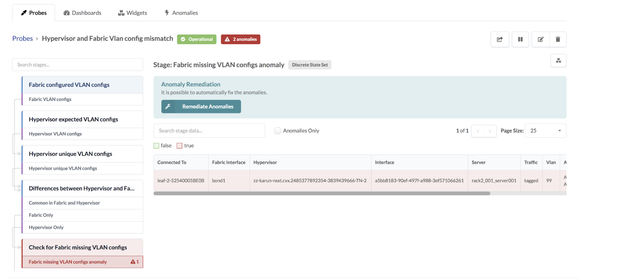
Some other reasons for mismatching include the following:
- If the configured VLAN NSX-T transport node is missing in the fabric.
- If the configured VLAN NSX-T transport node is in the fabric, but the end VMs or servers are not part of this virtual network or VLAN.
- If a segment is created in NSX-T for either an overlay or VLAN-based transport zone. It could be that the configured VLAN spanning the logical switch/segment on the transport node is missing on the fabric.
- If L2 bridging for VMs in different overlay logical segments is broken because one VM exists in one logical switch/segment and the other VM exists in a separate uplink logical switch/segment.
As an example, a VLAN is missing in NSX-T 3.0 Host Transport node on the Overlay
segment connected to ToR leaf devices and respective VXLAN VN is present in
Juniper Apstra Fabric and ports towards Hypervisors are assigned in a Virtual
Network based Connectivity Template as below:
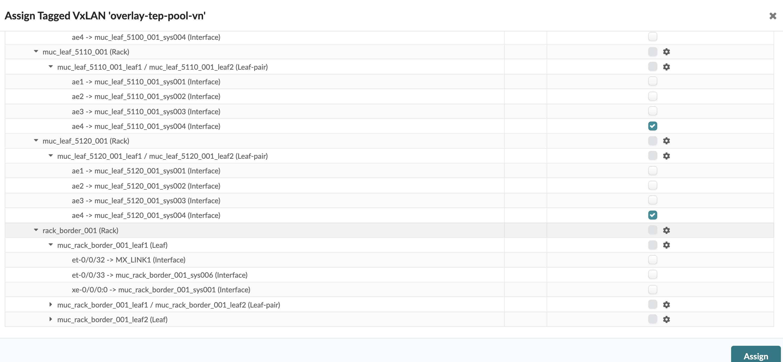
A Hypervisor missing VLAN Configs anomaly is raised as
shown below:
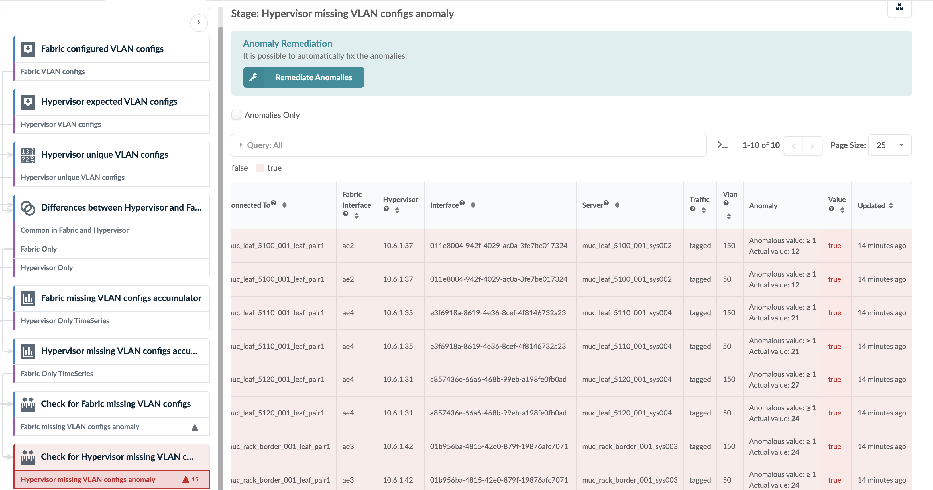
In some scenarios, a VLAN mismatch anomaly can be remediated. If so, the Remediate Anomalies button appears on the probe details page as shown in the screenshot above. Example scenarios include:
- NSX-T transport nodes use an uplink profile to define transport VLAN over which overlay tunnel comes up. Fabric could be missing the rack-local VN for transport VLAN on hypervisors. One-click remediation can be provided by creating a new rack-local virtual network with the proper VLAN ID in the fabric.
- A rack-local virtual network is defined with VLAN ID Y, however, the connected virtual infra nodes (i.e hypervisors) do not have the VLAN ID in the logical segment/switch. One-click remediation can be provided by removing the endpoint from the affected VLAN ID.
If the Remediate Anomalies button appears under the stage
name, you can click it to automatically stage the changes required to remediate
the anomaly. You can see the staged changes on the
Uncommitted tab.
Review the staged configuration, add any necessary resources (such as IP subnet address, virtual gateway IP, as so on), then commit the configuration.
Usage with VCenter Integration
Some anomalies, that are raised because of a VLAN config mismatch between vCenter and the fabric, can automatically be remediated, such as the following.
- If the vCenter Distributed Virtual Switch (vDS) port group does not have a corresponding rack-local VN (VLAN) for VLAN ID X. With one-click remediation, a new rack-local virtual network (VLAN) with the proper VLAN ID is created.
- If endpoint X in a rack-local VN with VLAN ID Y, does not have a corresponding dVS port group. With one-click remediation, the endpoint is removed from the affected VLAN ID.
Note
vCenter vDS must be used with VLAN specific ID allocation on the port group for L2 network segmentation at the hypervisor level.
A VLAN-based rack-local virtual network is extending each VLAN segment defined on the vDS, across servers within the same rack. For example, vDS port group VLAN 10 = rack-local virtual network with VLAN 10.
For more information about this probe, from the blueprint, navigate to Analytics > Probes, click Create Probe, then select Instantiate Predefined Probe from the drop-down list. Select the probe from the Predefined Probe drop-down list to see details specific to the probe.