What are Device Profiles
Device profiles define capabilities of supported hardware devices. Some feature capabilities have different behaviors across NOS versions and thus, capabilities are expressed per NOS version. By default, the version matches all supported versions. As additional hardware models are qualified, they are added to the list of qualified devices.
Device profiles (vendor-specific details of devices) are associated with logical devices (abstractions of physical details of devices) to create interface maps. When you build your blueprint you'll assign these interface maps to devices in your topology.
Device profiles are either monolithic or modular. The following sections describe device profile parameters. For additional information about device profiles, see Adding Device Profiles Using the Apstra UI.
Monolithic Device Profiles
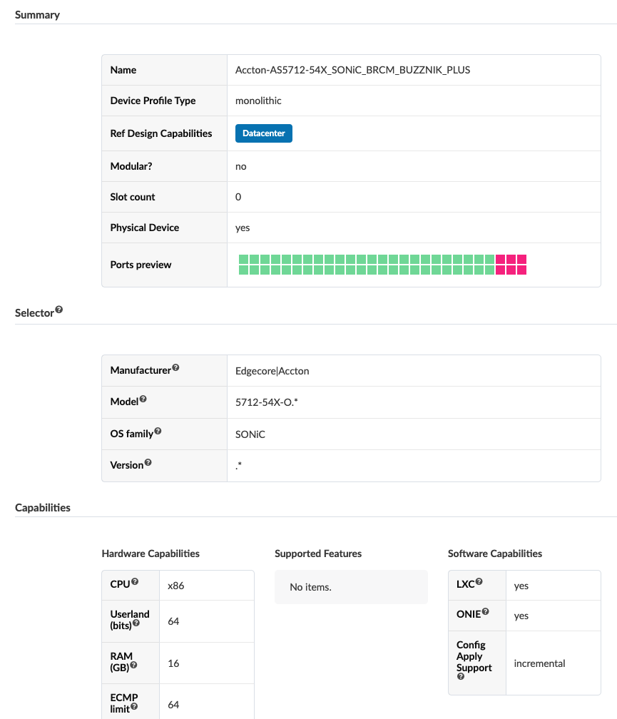
Summary
| Summary Section | Description |
|---|---|
| Type | Monolithic |
| Physical Device | Yes or No |
| Name | Name of device profile. 64 characters or fewer. |
| Ref Design Capabilities | Datacenter and/or Freeform |
| Chassis Profile | For modular device profiles only |
Selector
The Selector section contains device-specific information to match the hardware device to the device profile as described below:
|
Selector Section |
Description |
|---|---|
|
Manufacturer |
Selected from drop-down list |
|
Model |
Determines whether a device profile can be applied to specific hardware. Selected from drop-down list or entered as a regular expression (regex). |
|
OS family |
Defines how configuration is generated, how telemetry commands are rendered, and how configuration is deployed on a device. Selected from drop-down list. |
|
Version |
Determines whether a device profile can be applied to specific hardware. Selected from drop-down list or entered as regex. |
Capabilities
You can leverage the hardware and software capabilities defined in this section in other parts of the Apstra environment to adapt the generated configuration, or to prevent an incompatible situation. With the exception of ECMP, hardware capabilities modify configuration rendering or deployment. Capabilities include the following details:
|
Capabilities Section |
Description |
|---|---|
|
CPU (cpu:string) |
Describes the CPU architecture of the device. For example: "x86" |
|
Userland (bits) (userland:integer) |
Type of userland (application binary/kernel) the device supports. For example: "32" or "64". |
|
RAM (GB) (ram:integer) |
Amount of memory on the device. For example: "16" |
|
ECMP limit (ecmp_limit:integer) |
Maximum number of Equal Cost Multi Path routes. For example: "64". This field changes BGP configuration on the device (ecmp max-paths). |
|
Form factor (form_factor:string) |
Number of rack units (RU)s on the device. For example: "1RU", "2RU", "6RU", "7RU", "11RU","13RU" |
|
ASIC (asic:string) |
The switch chipset ASIC. For example: "T2", "T2(3)", "T2(6)", "Arad(3)", "Alta", "TH", "Spectrum", "XPliant XP80", "ASE2", "Jericho". Used to assist telemetry, configuration rendering and VXLAN routing semantics |
|
LXC (lxc_support: boolean) |
Selected if the device supports LXC containers. |
|
ONIE (onie: boolean) |
Selected if the device supports ONIE. |
COPP - When Control Plane Policing is enabled (COPP), strict CoPP profile config is rendered for the specified NX-OS version resulting in the following configuration rendering:
terminal dont-ask
copp profile strict
This terminal dont-ask config is needed only when enabling the CoPP profile strict config, since we do not want NX-OS to wait for confirmation:
switch(config)# copp profile strict
This operation can cause disruption of control traffic. Proceed (y/n)? [no] ^C
switch(config)#
switch(config)# terminal dont-ask
switch(config)# copp profile strict
switch(config)#
CoPP is enabled by default, except for Cisco 3172PQ NXOS. You can specify multiple versions.
Breakout - Enable breakout to indicate that ports on specified modules can be broken out to lower speed split ports.
Apstra
software first un-breakouts all ports that are breakout-capable, and then applies the proper
breakout commands according to intent. This is based on the assumption that the global
negation command no interface breakout module<module_number> can
always be applied successfully to a module with breakout capable ports. (This is idempotent
when applied on ports that are not broken out.) However, we recognize that this assumption
may be broken in future versions of NX-OS, or with a certain combination of cables /
transceivers inserted into breakout-capable ports.
The example below is for the negation command for a module (1) that is set to True:
no interface breakout module 1
!
Since the negation command is always applicable per module, each module is specified individually. The advantages of this include:
- In modular systems, not all line cards have breakout capable ports.
- In non-modular systems, the breakout capable ports may not always be in module 1.
Breakout is enabled by default except for the following devices with modules incapable of breaking out ports: 3172PQ NXOS, 9372TX NXOS, C9372PX NXOS, C9396PX NXOS, NXOSv.
Historical Context - With a particular version of NX-OS the POAP stage would apply breakout config on those ports which are breakout capable. POAP behavior, introduced in 7.0(3)I4(1) POAP, determines which breakout map (for example, 10gx4, 50gx2, 25gx4, or 10gx2) brings up the link connected to the DHCP server. If breakout is not supported on any of the ports, POAP skips the dynamic breakout process. After the breakout loop completes, POAP proceeds with the DHCP discovery phase as normal. Apstra reverts any such breakout config that might have been rendered during the POAP stage to ensure that the ports are put back to default speed by applying the negation command.
Sequence Numbers Support - Applicable to autonomous system (AS) path. Enable when the device supports sequence numbers. Apstra sequences into the entry list to resequence and generate config as follows:
ip as-path access-list MyASN seq 5 permit ^$
ip as-path access-list Rtr seq 5 permit ^3
ip as-path access-list Srvr seq 15 permit _103$
The numbers 5 and 15 are sequence numbers applicable to devices that support AS sequencing.
Sequence numbers support is enabled for all Cisco device profiles by default (except Cisco 3172PQ NXOS, which does not support sequence numbers). For platforms that do not support sequence numbers, disabling this feature ensures that the AS sequence numbers are removed from the device model dictionary to avoid addition and negation in the event that something is resequenced. This scenario has no requirement to render anything on these platforms, because the entry can't be sequenced.
Other supported features - not available from the Apstra GUI include "vxlan", "bfd", "vrf_limit", "vtep_limit", "floodlist_limit", "max_l2_mtu", and "max_l3-mtu". They can be included in the backend using the following format:
key : value :: feature : feature_properties Example: 32 vtep_limit: 32
Ports
The ports section defines the types of available ports, their capabilities and how they are organized.
Every port contains a collection of supported speed transformations. Each transformation represents the breakout capability (such as 1-40GBe port breaking out to 4-10GBe ports), and hence contains a collection of interfaces.
Example: If port 1 is a QSFP28 100->4x10, 100->1x40 breakout capable port, then port 1 has a collection of three transformations, one each for 4x10, 1x40 and 1x100 breakouts. The transformation element in the collection which represents the 4x10 has a collection of 4 interfaces, 1x40 and 1x100 has a collection of 1 interface.
Ports parameters include the following details:
|
Ports Section |
Description |
|---|---|
|
Port Index (port_id: integer) |
Indicates a unique port in the collection of ports in the Device Profile. |
|
Row Index (row_id: integer) |
Represents the top-to-bottom dimensions of the port panel. Shows where the port is placed in the device's panel. For instance, in a panel with two rows and many columns the row index is either "1" or "2". |
|
Column Index (column_id: integer) |
Represents the left-to-right dimensions of the port panel. Shows where the port is placed in the device's panel. For instance, in a panel with thirty-two ports and two rows, the column index is in the range of "1" through "16". |
|
Panel Index (panel_id: integer) |
Indicates the panel that the port belongs to given the physical layout of ports in the device specification |
|
Slot ID (slot_id: integer) |
Represents the module that the port belongs to. A modular switch has more than one slot. In fixed function network function devices, Slot ID is usually "0". |
|
Failure Domain (failure_domain_id: integer) |
Indicates if multiple panels are relying on the same hardware components. Used when creating the cabling plan to ensure that two uplinks are not attached to the same failure domain. |
|
Connector Type (connector_type: string) |
Port transceiver type. Speed capabilities of the port are directly related to the connector type, given that certain connector types can run in certain speeds. For instance, "sfp", "sfp28", "qsfp", "qsfp28". |
|
Transformations (transformations: list) |
Possible breakouts for the port. Every entry is a specific supported speed. Each transformation has a collection of interfaces. |
|
Number of interfaces (interfaces:list) |
Dependent on the breakout capability of the port. For a transformation representing a certain breakout speed, the interfaces contain information about the interface names and interface settings with which the device intends to be configured. The "setting" information is crucial for configuring the interfaces correctly on the device. |
Based on the OS information entered in the device profile's selector field, the Apstra GUI displays the applicable settings fields. The fields vary with the vendor OS (as found in examples below). When a device profile is created or edited, the "setting" is validated from the vendor-specific schema as listed below.:
eos_port_setting = Dict({
    'interface': Dict({
        'speed': Enum([
            '', '1000full', '10000full', '25gfull', '40gfull',
            '50gfull', '100gfull',
        ])}),
    'global': Dict({
        'port_group': Integer(),
        'select': String()
        })
    })

nxos_port_setting = Dict({
    'interface': Dict({
        'speed': Enum([
            '', '1000', '10000', '25000', '40000', '50000',
            '100000',
        ])}),
    'global': Dict({
        "port_index": Integer(),
        "speed": String(),
        "module_index": Integer()
        })
    })

junos_port_setting = Dict({
    'interface': Dict({
        'speed': Enum([
            '', 'disabled', '1g', '10g', '25g', '40g', '50g', '100g'
        ])}),
    'global': Dict({
        'speed': Enum([
            '', '1g', '10g', '25g', '40g', '50g', '100g'
        ]),
        "port_index": Optional(Integer()),
        "fpc": Optional(Integer()),
        "pic": Optional(Integer())
        })
    })

sonic_port_setting = Dict({
    'interface': Dict({
        "command": Optional(String()),
        "speed": String(),
        "lane_map": Optional(String())
        })
    })
})
Apstra does not necessarily use all the information above for modeling. It's made available to other Apstra API orchestration tools for collection and use.
Modular Device Profiles
Summary
|
Type |
Modular |
|
Name |
Name of device profile. 64 characters or fewer. |
| Chassis Profile |
The chassis profile to associate with the DP |
Device Profiles in the Apstra GUI
From the left navigation menu in the Apstra GUI, navigate to Devices > Device Profiles to go to the device profile table view.
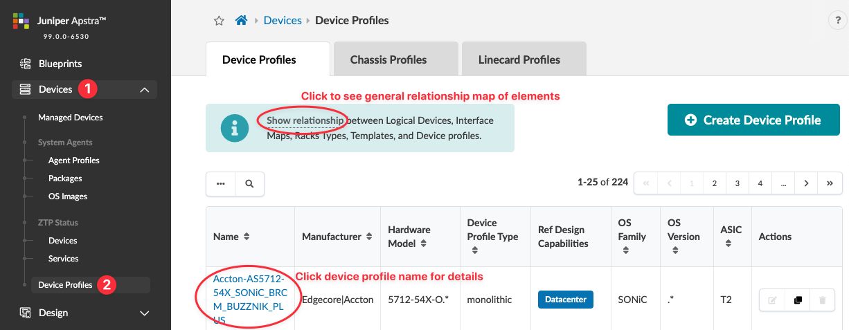
To see how Apstra device profiles and design elements are related to each other, click Show relationship (new in Apstra version 5.0.0). This is helpful if you're new to the Apstra environment.

Many device profiles are predefined for you. To search for a device profile, click the Search button (magnifying glass) and enter your criteria.
Click a device profile name to go to its details.
You can create, edit, and delete device profiles.