Transmit Power Notation for Juniper APs
Radio Power Levels and Conversions
Radio resource management (RRM) provides sophisticated radio and antenna power management when enabled and set to auto, and we recommend that you use it. See Radio Resource Management (RRM). However, if you need to configure the settings manually or just want to understand the power calculations and values, the following explanation will help.
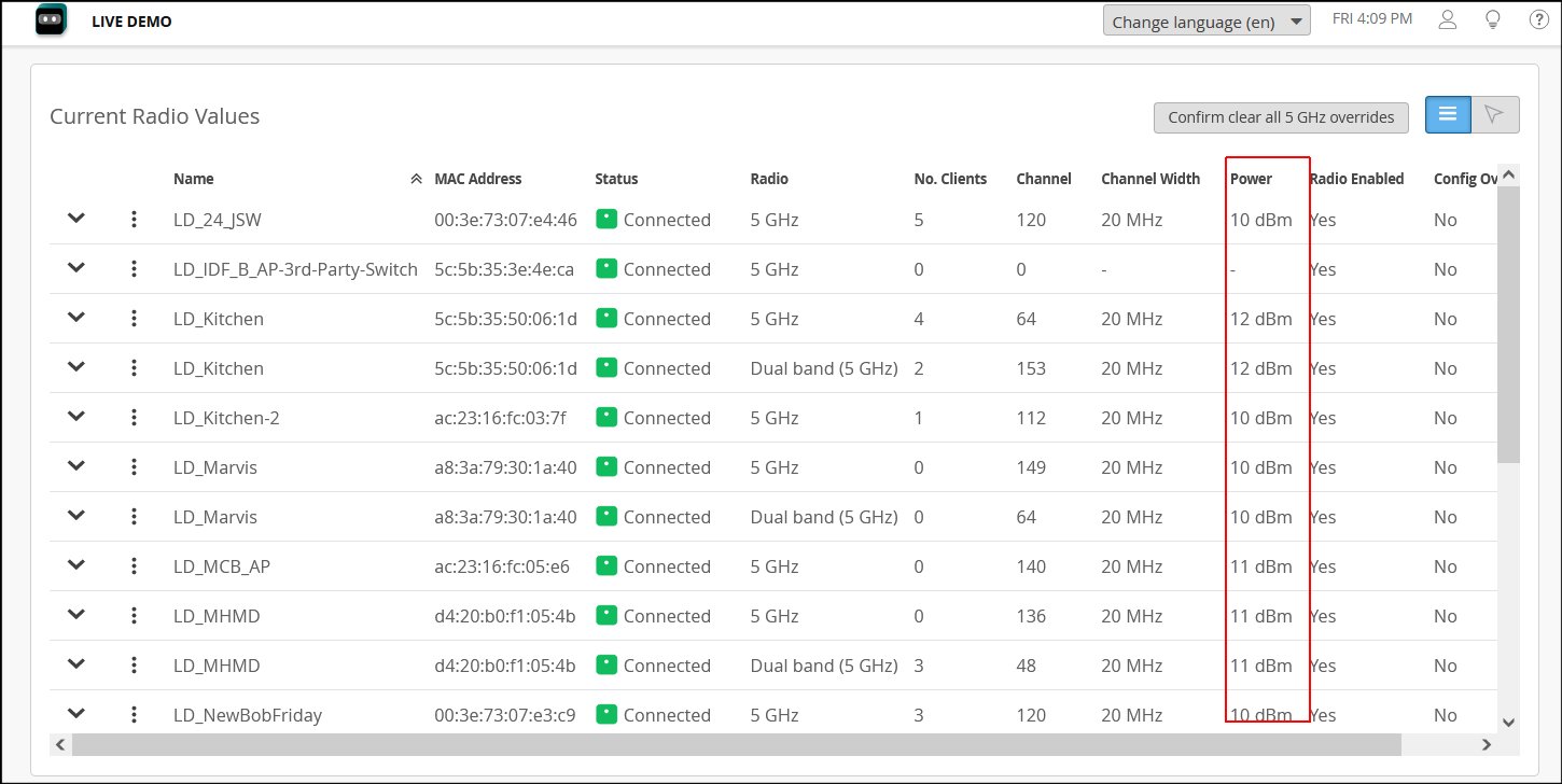
- In Juniper Mist, the power values used are for the total AP transmit power of the entire transmit (Tx) chain.
-
Transmit power for the 6-GHz band is limited by the power spectral density (PSD) in the United States (and some other regulatory domains) rather than by Effective Isotropic Radiated Power (EIRP). EIRP is a calculated value used to represent transmitter output power, cable loss, and antenna gain.
-
For transmit power, when using multiple-input multiple-output (MIMO) gains from a wireless design tool, you may need to adjust those values before using them in the Mist portal. Both the reason and the adjustment are explained in the Working with Wireless Design Tools section at the end of this topic.

- Rule of Thumb for MIMO Gain Values
- Calculating TPO and EIRP
- EIRP (for 6-GHz band radios)
- Converting Between PSD and EIRP
- Working with Wireless Design Tools
Rule of Thumb for MIMO Gain Values
A simple rule of thumb for manual settings for AP41, AP43, and AP45 devices is to add 6 dB for MIMO gain. For AP34 devices, add 3 dB. In terms of radios, the rule of thumb looks like this:
- 4 spatial streams (4x4): 6 dB of MIMO gain
- 3 spatial streams (3x3): 4.7 dB of MIMO gain
- 2 spatial streams (2x2): 3 dB of MIMO gain
| AP | Type | 2.4-GHz | 5-GHz |
| AP32E | Directional | 8 dBi | 10 dBi |
| Omni | 4 dBi | 6 dBi | |
| AP41E | Directional | 8 dBi | 8 dBi |
| Omni | No cert, use AP41 | No cert, use AP41 | |
| AP43E | Directional | 8 dBi | 10 dBi |
| Omni | 4 dBi | 6 dBi | |
| AP61E | Directional | 8 dBi | 8 dBi |
| Omni | 4 dBi | 6 dBi | |
| AP63E | Directional | 8 dBi | 10 dBi |
| Omni | 4 dBi | 6 dBi |
Calculating TPO and EIRP
The total power output (TPO) for Juniper APs is equal to the transmit power per radio chain, plus the log value of the total number of radio chains. Radio chains are comprised of the transceiver, antenna, and hardware needed for signal processing.
- TPO = Tx power per chain + 10log (Tx chains)
So, for example, if you have a Juniper AP with 17 decibel-milliwatts (dBm) per chain, you add 6 dB MIMO gain for a total transmit power of 23 dBm.
Calculating the EIRP, which is a value for the estimated output power radiated by the antenna, is similar:
- EIRP = TPO + antenna gain - antenna losses
EIRP (for 6-GHz band radios)
Some regulatory domains, including the United States, use PSD rather than EIRP for radio transmit power limits. With PSD, the power density decreases as channel bandwidth increases.
For a fuller understanding of PSD and an illustration comparing EIRP and PSD across channel bandwidths, see: https://blogs.juniper.net/en-us/industry-solutions-and-trends/power-spectral-density.
In addition:
-
Wide channel width settings, such as 80 MHz, can yield higher EIRP than narrow channel width settings like 20 and 40-MHz.
-
In the United States, the FCC allows up to 5 dBm/MHz PSD, or up to 30 dBm EIRP for low power indoor (LPI) operations.
-
In the EU, regulators allow up to 10 dBm/MHz PSD, or up to 23 dBm EIRP for LPI.
Converting Between PSD and EIRP
EIRP is equal to PSD plus the log of the total channel width. You can use the formula shown here to convert between PSD and EIRP:
- EIRP = PSD + 10log (channel width)
So, if, for example, you have a PSD of 5 dBm/MHz and 40-MHz channels, the EIRP would be 5 + the base 10 log of 40, which is 1.6, for a total dBm of 21.
| Channel Width | PSD | EIRP | Noise Floor | Net EIRP | Available Channels |
|---|---|---|---|---|---|
| 20-MHz | 5 dBm/MHz | 18 dBm | na | 18 dBm | 59 |
| 40-MHz | 5 dBm/MHz | 21 dBm | +3 dBm | 18 dBm | 29 |
| 80-MHz | 5 dBm/MHz | 24 dBm | +6 dBm | 18 dBm | 14 |
| 160-MHz | 5 dBm/MHz | 27 dBm | +9 dBm | 18 dBm | 7 |
| 320-MHz | 5 dBm/MHz | 30 dBm | +12 dBm | 18 dBm | 3 |
Working with Wireless Design Tools
Some wireless design tools consider total transmit power to be the combination of all transmitters on the AP (the total power out), whereas in the Mist portal, the value does not include the cumulative MIMO gains. Thus, to convert the transmit power from one of those tools to Mist transmit power, you must subtract the MIMO gain.
For example, say that you see a value of 14 dBm for the simulated transmit power of a Mist AP43. When setting power in the Mist portal, you would set 8 dBm (14 dBm TPO - 6 dBm MIMO gain.)
In another example, consider two simulated APs, where one is a 1×1:1 and the other is a 4×4:4 (one radio vs four). Transmit power for both APs is set at 14 dBm. In a design tool, because the software does not take into consideration the number of transmitters in the AP, the predicted transmit radius of both APs would be the same.
