Wireless Mesh Network Configuration
To cover a wider area than a single AP could do on its own, consider configuring a wireless mesh network.
A mesh network is a group of connectivity devices, such as APs that act as a single network. With a mesh network, you can have multiple sources of connectivity around your location instead of a single point of access.
Using APs in mesh mode expands the coverage area for your deployment. APs leverage neighboring APs to relay traffic to and from a base AP that is connected to the access switch.
Mist supports single hop mesh—the interconnection between the APs is single, wireless hop, and occurs automatically after setup. In a mesh, APs are classified as a base or relay. A base has an Ethernet connection to an uplink switch. The relay AP connects to the base AP through a wireless mesh link. If a base AP goes offline, the relay APs can automatically failover to another base AP. You can create mesh groups so that a base AP will only accept failovers from relay APs that are members of a given group.
Mist also supports mesh on Dynamic Frequency Selection (DFS) channels. DFS channels are a group of channels that are located in the UNII-2 and UNII-2-extended bands where Wi-Fi coexists with Doppler weather radar, commonly located in airports. The AP switches to a new channel if it detects radar, in which case it will advertise a Channel Switch Announcement. When switching channels, if the AP selects a non-DFS channel, it begins sending Wi-Fi beacons right away (these beacons advertise the available SSID and data rates). However, if the new channel is another DFS channel, the AP will perform a 60-second channel availability check (CAC) before sending any beacons.
Enable Wireless Mesh
Before you set up a mesh, ensure that all the APs have a wired connection to the Mist cloud so that they can receive the configuration. After that, you can disconnect wired links from the APs.
If you intend to set up wireless mesh at scale, we recommend that you use device profiles to save time and simplify management. In such as case, you would create one profile for the base APs and another for the relay APs and then attach the various APs to the correct device profile according to role.
To enable wireless mesh:
Enable mesh networking at the site level:
From the left menu of the Juniper Mist portal, select Organization > Site Configuration.
The Site Configuration page appears.
Click a site.
Scroll down to the Wireless Mesh section of the page and select the Enable mesh networking check box.
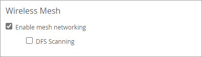
If you enable DFS scanning, the relay AP will scan for the base APs on both DFS and non-DFS channels.
Click Save in the upper-right corner of the page.
Designate the base and relay APs:
- From the Mist portal, click Access Points.
Click an AP.
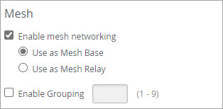
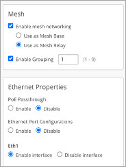
Scroll down to the Mesh section.
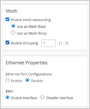
- Select Enable mesh networking.
- Choose the role you want for the AP, base or relay:
- Use as a Mesh Base (AP must have a cable connection to the access switch).
- Use as a Mesh Relay (AP will transit both client traffic, and management traffic, through a base AP).
-
(Optional, to control failover with multiple mesh links in a site) Click Enable Grouping and enter a group number (1 through 9) to control which relay APs can failover to a given base AP.
You can create mesh groups so that a base AP will only accept failovers from relay APs that are members of a given group. Assign a group number (1 through 9) to the relay APs, and then configure the base AP to only accept failover connections from relay APs with that group number.
-
Click Save in the upper-right corner of the page.
After you configure an AP as a relay AP, wait for a few seconds before removing its wired uplink to the switch. Ensure that the relay AP is connected to a power adapter
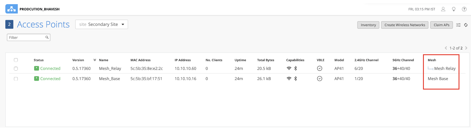
The relay AP will now be connected to the base AP. In the Access Points page, you can see which of your APs are set as base and relay. You'll need to enable the Mesh column in the display menu.
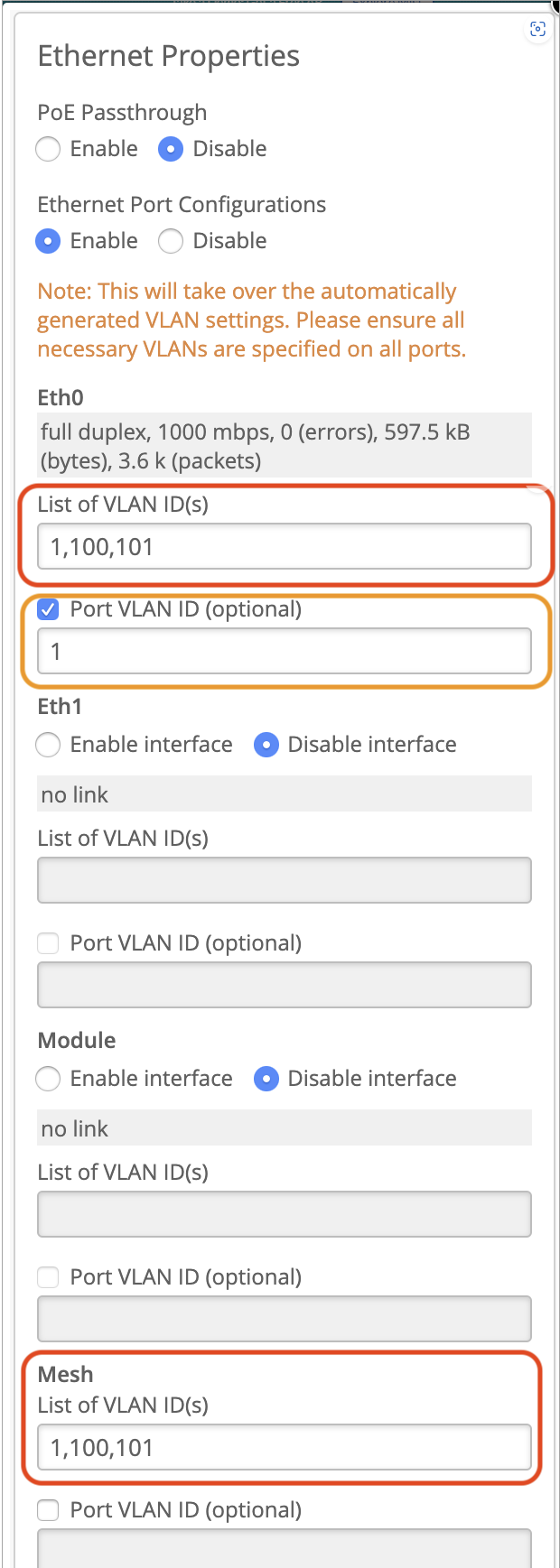
If you have any SSIDs broadcasting on the relay AP but not on the base AP, specify the SSID VLAN ID(s) on the Eth0 or Eth1 port of the base AP in the Ethernet Properties section.
Here's an example that shows the Eth0 settings on the base AP with VLAN IDs 1, 100, and 101. VLAN 1 is the management VLAN of the AP. You must specify this value in the Port VLAN ID field or else the AP will disconnect from the cloud. VLAN 100 and VLAN 101 are for tagged SSIDs, which are broadcasting on the relay AP but not on the base AP.
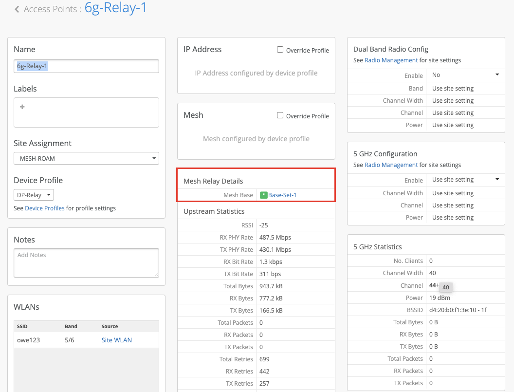
The AP configuration page for the base and relay APs display the mesh details if the mesh is set up correctly. In the following example, you'll see the details of the relay APs on the base AP configuration page.
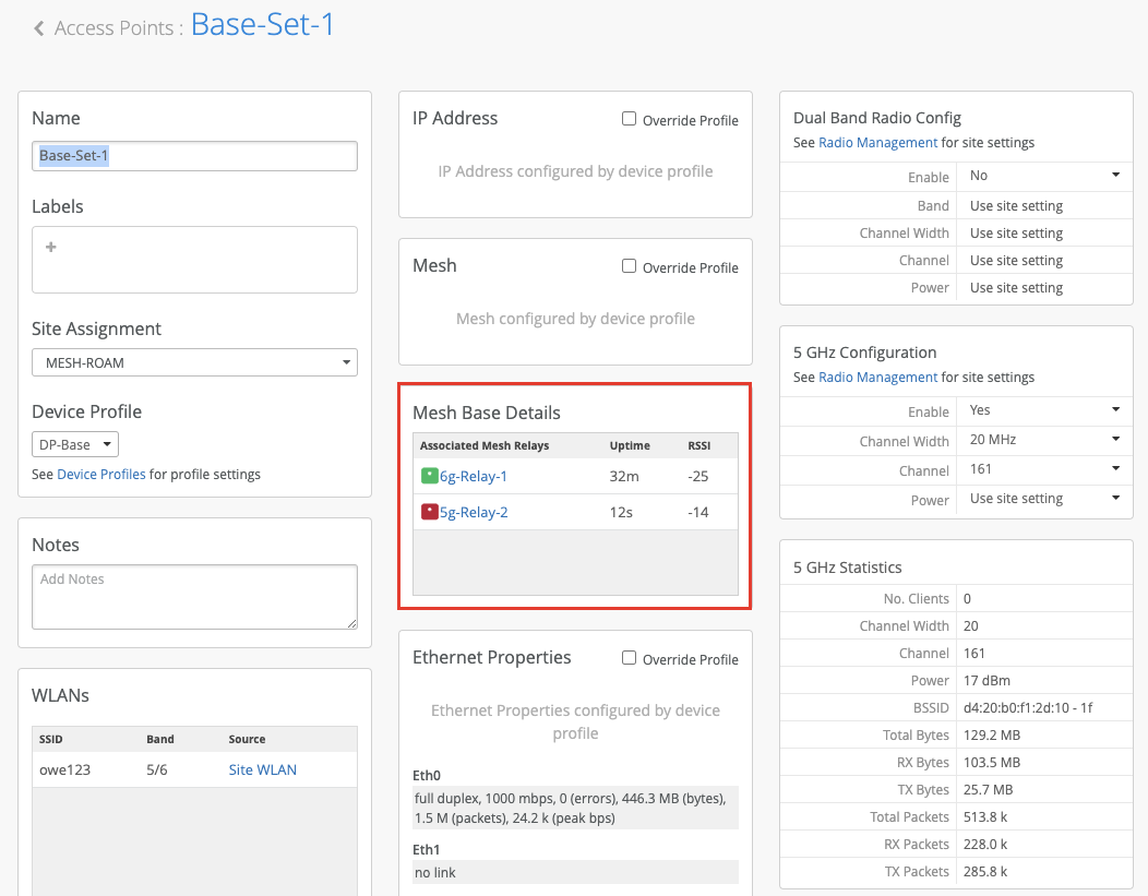
Similarly, the configuration page for the relay AP will display the details of the base AP that it connects to.
AP Mesh Use Cases
Use Case 1: Extend WLANs over Mesh
In this use case, all the required VLANs in the network are being tagged in the SSIDs.
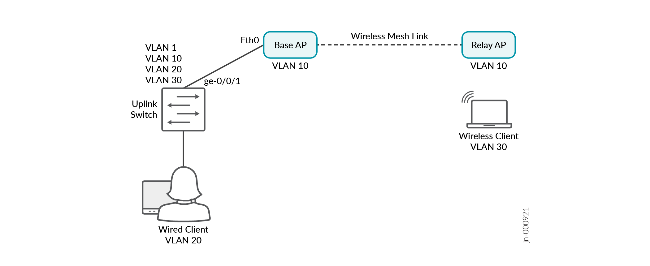
Topology
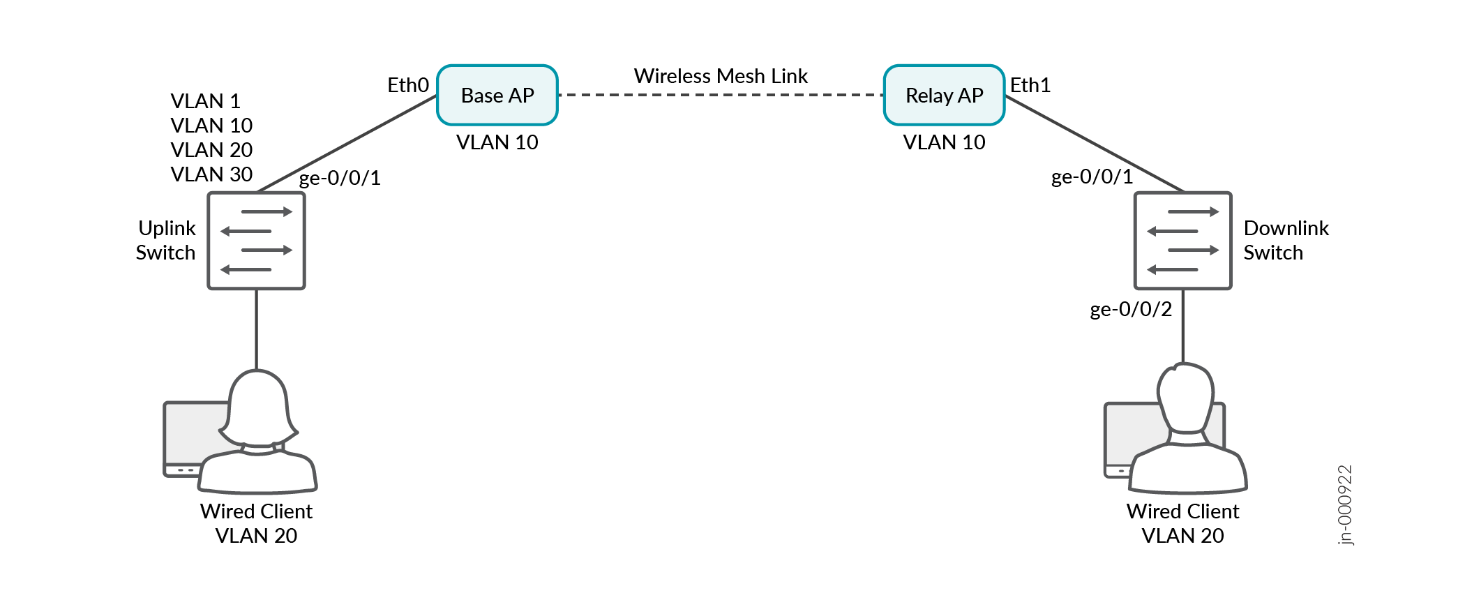
The uplink switch interface ge-0/0/1 has a wired connection to the base AP, which has a wireless mesh link to the Relay AP.
Requirements
-
Uplink switch VLANs (where the base AP gets connected) = 10,20,30
-
Management VLAN (through which the APs will get the IP address)= 10
-
Wireless SSID B= tag with VLAN 30
-
Wireless client should get an IP address from VLAN 30.
-
Both base and relay APs should get an IP from the management VLAN 10.
Procedure
Configure the uplink switch port by using the following commands:
set interfaces ge-0/0/1 native-vlan-id
                                    10
set interfaces ge-0/0/1 unit 0 family ethernet-switching interface-mode trunk vlan members [10,30]See Add or Delete a CLI Configuration for information about adding CLI configurations to a switch from the Mist portal.
Designate the base AP in the AP configuration page as shown.
Designate the relay AP in the AP configuration page as shown:
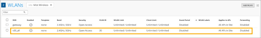
Configure the WLAN for the wireless clients to connect to the base or relay AP. In this example, the clients will obtain an IP address from VLAN 30.
Use Case 2: Connecting a Switch on a Relay AP
In this scenario, we need to connect a switch on a relay AP and configure a VLAN on a downlink switch that is not being tagged in the SSIDs.
Topology
The uplink switch interface ge-0/0/1 has a wired connection to the base AP, which has a wireless mesh link to the relay AP. The relay AP connects to a downlink switch on interface ge-0/0/1. A PC on an access port configured with VLAN 20 connects over interface ge-0/0/2 on the downlink switch.
The configuration for this use case is similar to Use Case 1, but we also need to enable the Ethernet port configurations in order to pass VLAN 20, which is not in the wireless network.
Requirements
-
The Wired PC on the downlink switch should get its IP from VLAN 20.
-
No wireless SSID is tagged on VLAN 20.
-
Wireless clients get IPs on VLAN 30.
-
Switches and APs get IPs on VLAN 10.
Procedure
Configure the uplink switch ports by using the following commands:
ge-0/0/1
set interfaces ge-0/0/1 native-vlan-id
                                                  10
set interfaces ge-0/0/1 unit 0 family ethernet-switching interface-mode trunk vlan members [1,10,20,30]
See Add or Delete a CLI Configuration for information about adding CLI configurations to a switch from the Mist portal.
Configure two ports on the downlink switch port:
ge-0/0/1
set interfaces ge-0/0/1 native-vlan-id
                                                  10
set interfaces ge-0/0/1 unit 0 family ethernet-switching interface-mode trunk vlan members [1,10,20,30]
ge-0/0/2
set interfaces ge-0/0/2 unit 0 family
                                                  ethernet-switching interface-mode access vlan
                                                  member 20
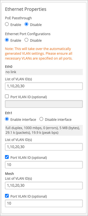
Designate the base AP. Enable mesh, as in Use Case 1. Also enable Ethernet port configurations and enter the settings.
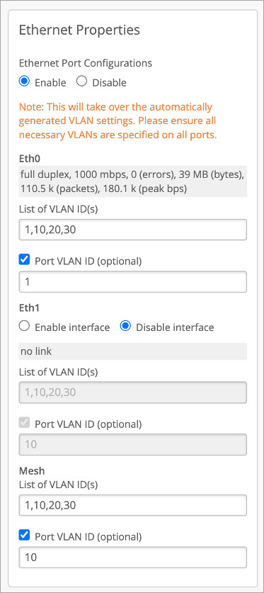
Designate the relay AP. Enable mesh, as in Use Case 1. Also enable Ethernet port configurations and enter the settings. In this example, you'll see that wired clients connecting to Eth1 on the relay AP will get the IP address on VLAN 10.
Configure the WLAN:
FAQs: AP Mesh Configuration
- Can I configure a mesh using different AP models?
- Can I configure a mesh using APs running different firmware versions?
- Can I deploy one mesh relay AP for multiple mesh base APs? If yes, how many mesh base APs can be deployed? Will the mesh base APs support failover?
- Will clients connected to a mesh relay AP have a lower throughput than clients connected to a mesh base AP?
- What is the recommended distance between a mesh base AP and a mesh relay AP?
Can I configure a mesh using different AP models?
Yes.
Can I configure a mesh using APs running different firmware versions?
We recommend that you use APs running the same firmware version.
Can I deploy one mesh relay AP for multiple mesh base APs? If yes, how many mesh base APs can be deployed? Will the mesh base APs support failover?
Yes, it is possible to deploy multiple mesh relay APs on one mesh base AP. We recommend not to exceed 4 mesh relay APs, which we have tested in our environment. A failover from one base AP to another can occur if the signal is weak or if the first base AP goes down.
Will clients connected to a mesh relay AP have a lower throughput than clients connected to a mesh base AP?
If both the mesh and client are on the 5 GHz band, the bandwidth available for the client is shared. Although the bandwidth is shared, it has a minimal impact on the overall throughput. Mist supports only single hop mesh. In multihop mesh, bandwidth is reduced at every mesh hop.
What is the recommended distance between a mesh base AP and a mesh relay AP?
The distance is dependent on the AP models and antenna types.