Create Generic System
Systems that are not managed by Apstra, like external routers and firewalls, are called generic systems. You specify their roles with tags. If the system is part of a rack topology we call it a generic system.
Add Generic System (from Topology View)
-
From the blueprint, navigate to Staged > Physical >
Topology and select the leaf or access switch to connect to
the new generic system.
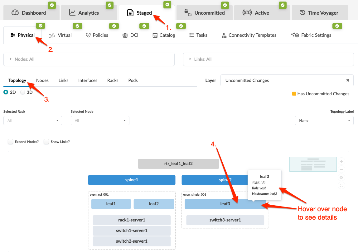
-
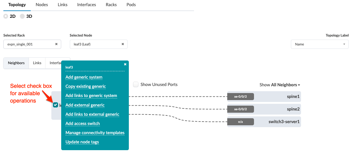
Select the node check box to see the operations available for that node
(and that you have permissions for).
(Image
below is for Apstra version 4.2.0.)
 Note:
Note:You can also get to the selection page from the Nodes view. From the blueprint, navigate to Staged > Physical > Nodes, click the node name in the table, then click the node name that appears at the top of the Selection panel (on the right side of the page).
-
If
you're using Apstra version 4.2.0,
click
Add generic system.
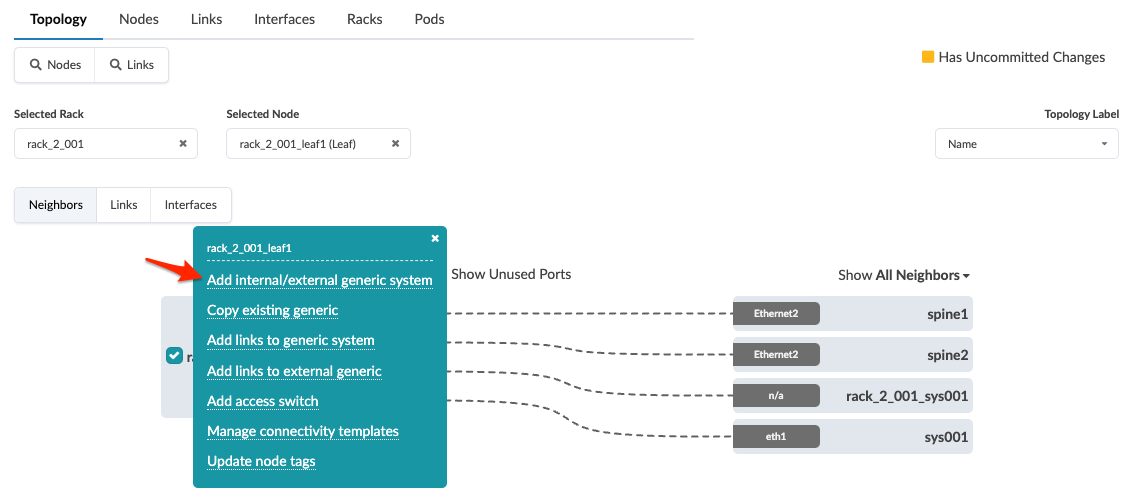
If
you're using Apstra version 4.2.1, click Add internal/external
generic system as shown in the 4.2.1 screenshot
below.
-
Enter
a unique label and (optional) hostname.
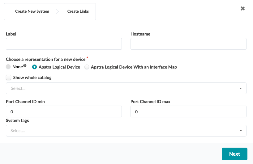
-
Enter tags (optional) to identify the role(s) of the new generic system,
then click Next.
-
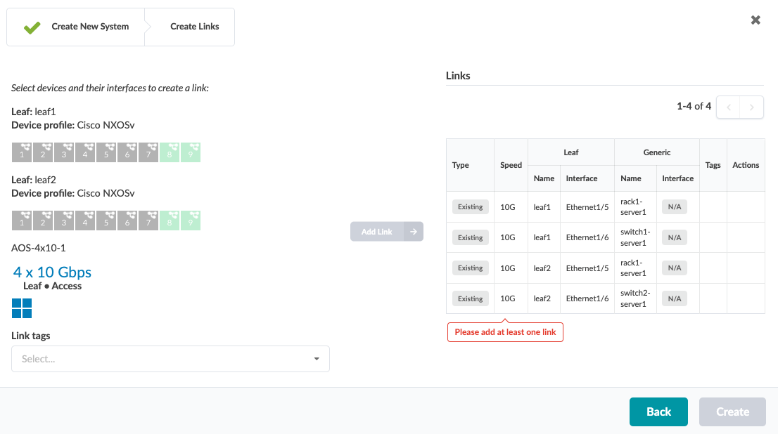
Select an available port and transformation. The gray Add
Link button turns green.
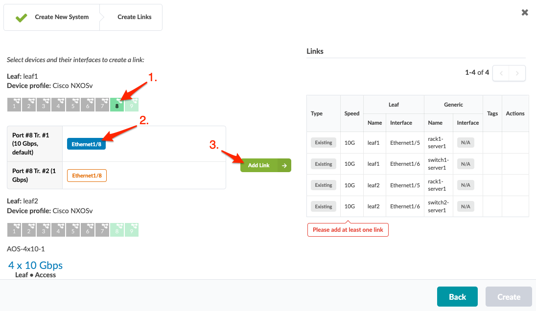
-
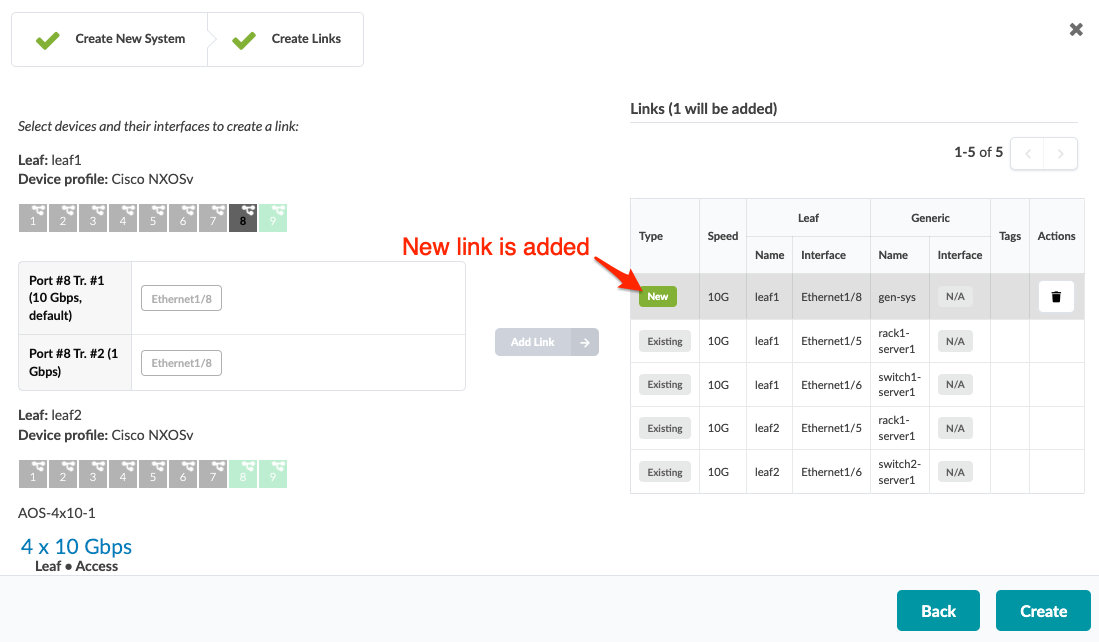
Click Add Link. The link is added to the link
table.
When you're ready to activate your changes, commit them from the Uncommitted tab.
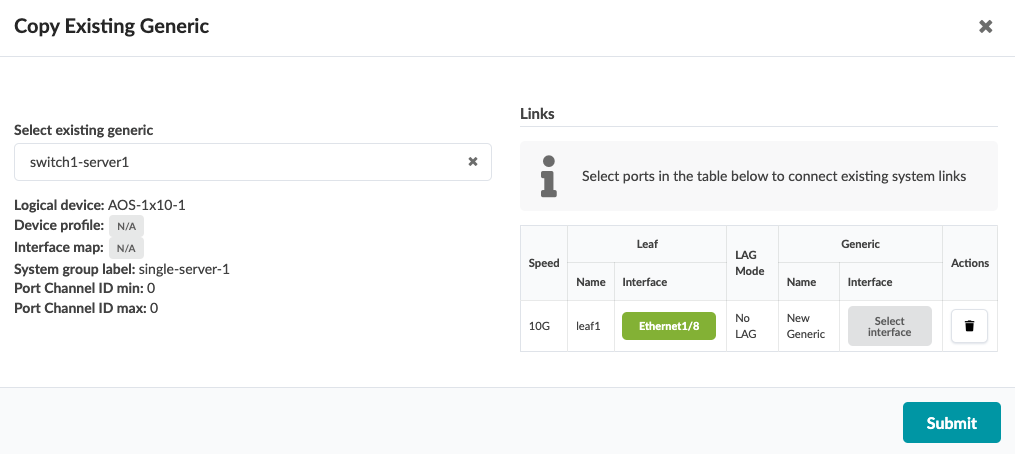
Copy Existing Generic System (from Topology View)
-
From the blueprint, navigate to Staged > Physical >
Topology and select the leaf or access switch that's
connected to the generic system that you want to clone.
-
Select the node check box to see the operations available for that node
(and that you have permissions for).
Note:
You can also get to the selection page from the Nodes view. From the blueprint, navigate to Staged > Physical > Nodes, click the node name in the table, then click the node name that appears at the top of the Selection panel (on the right side of the page).
-
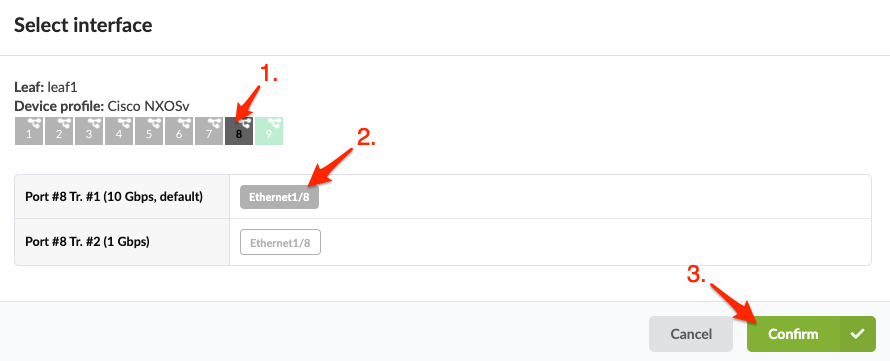
Click Select interface to go to ports.
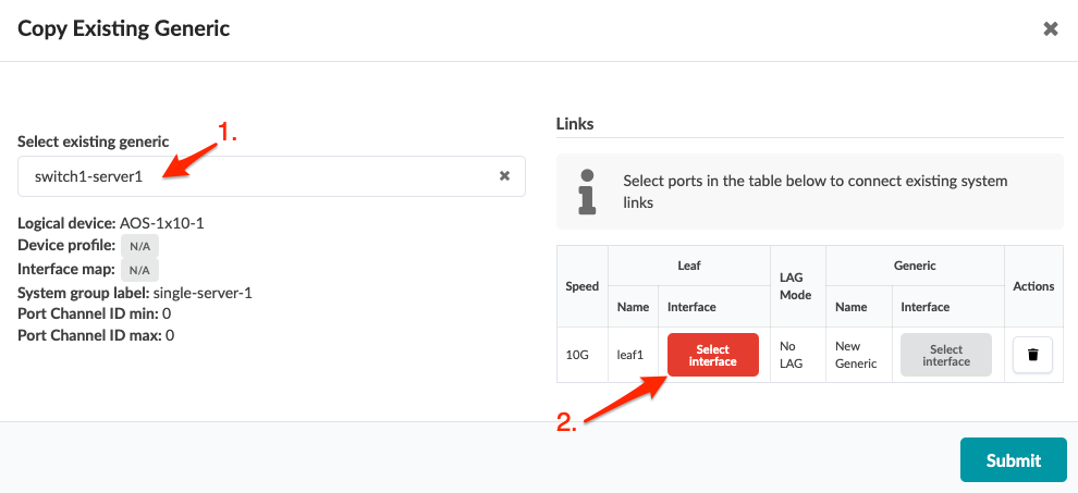
-
Select a port and transformation, then click Confirm
to return to the dialog.
-
Click Submit to stage the change and return to the
Topology view.
When you're ready to activate your changes, commit them from the Uncommitted tab.
You can also create generic systems when you create rack types during the Design phase.