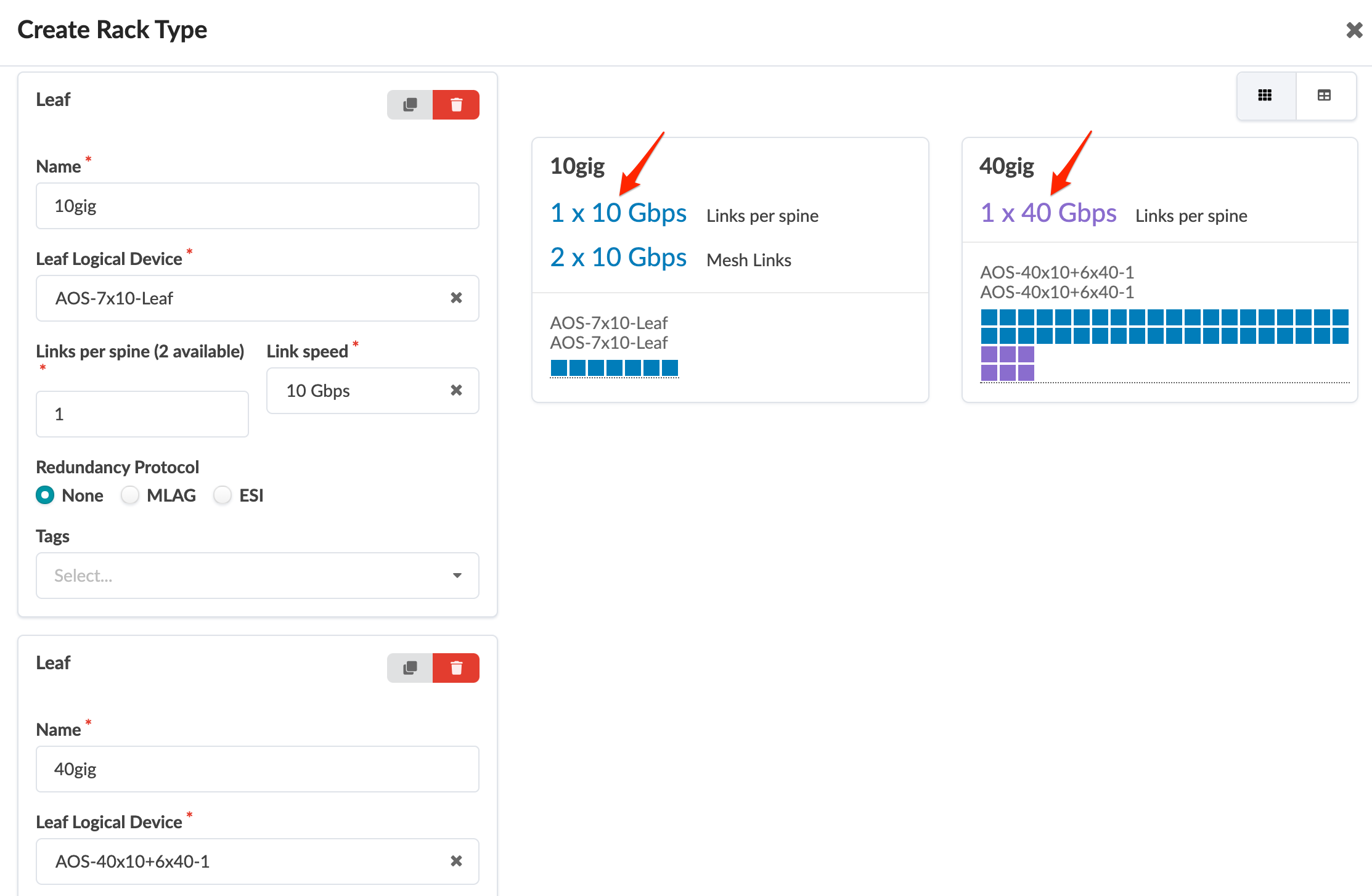
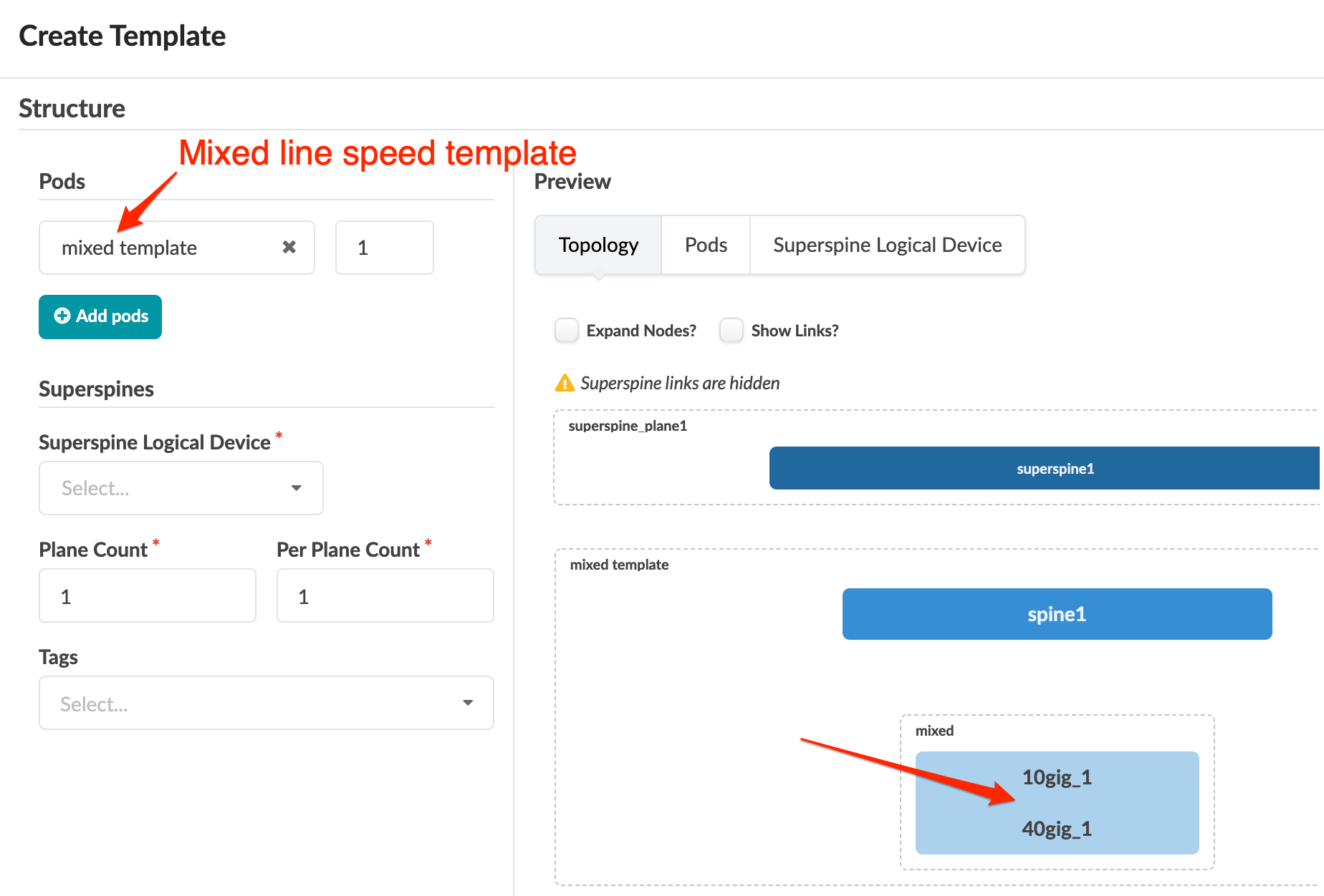
Mixed Link Speeds between Leaf and Spine
The leaf devices in your racks can have different uplink speeds to a spine. When designing for mixed speeds, make sure you plan sufficient ports for spine-to-leaf connections with mixed link speeds for Day 0, and for adding racks as a Day 2 operation. The spine logical device must have mixed port speeds defined that specify the port role as Leaf for the required number of ports. The following limitations apply:
- Parallel links between the same devices cannot have mixed speeds.
- You can't update spine logical devices if they're used in a blueprint. You could possibly use the AOS-CLI utility for manual patching. AOS-CLI is an experimental tool and it may not be able to provide a solution. For assistance, contact Juniper Support.
The example below shows how to design rack types and templates with mixed speeds.
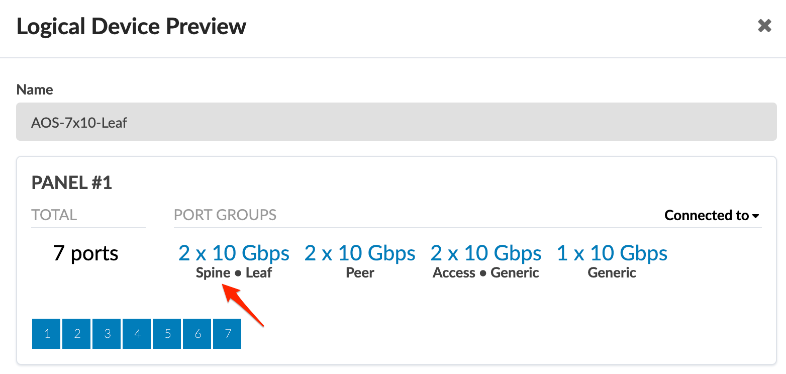
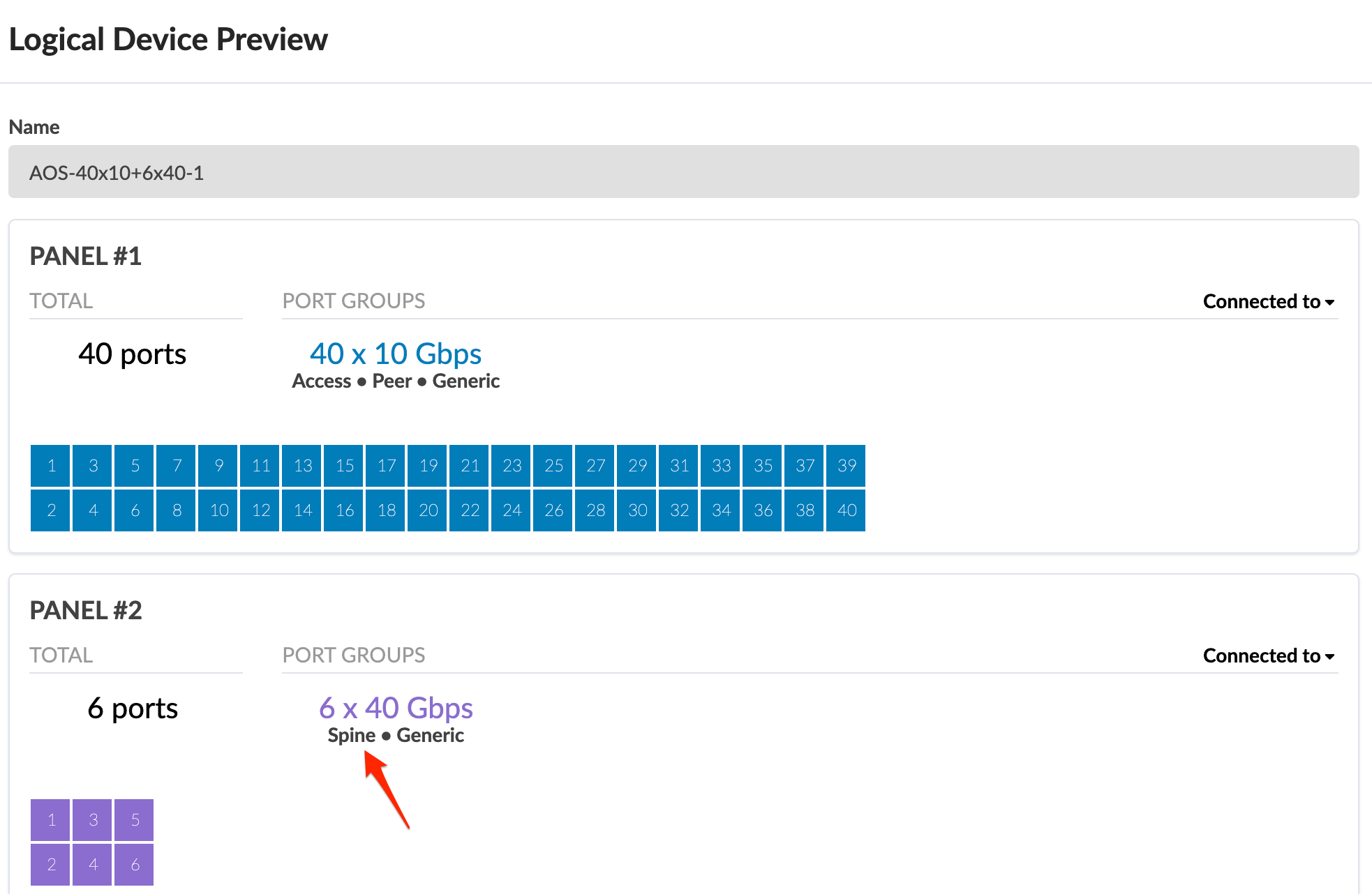
- Create an L3 Clos rack type with logical devices AOS-7x10-Leaf and
AOS-40x10+6x40-1 for two leaf switches, having 10 GbE and 40GbE,
respectively, as uplinks towards spine devices
- Create a Rack Based template based on the mixed speed rack type.
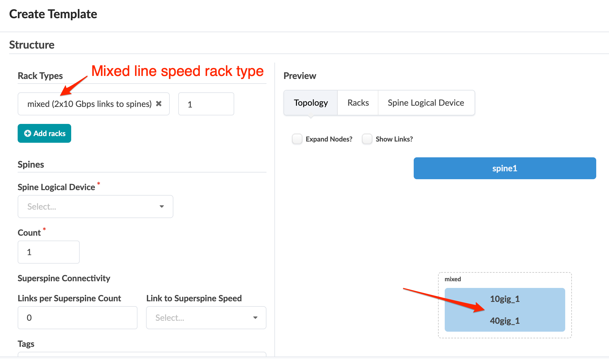
- You can create a Pod Based template based on the above rack based
template.
- As a Day 0 operation you can create a blueprint with one of the above templates; or as a Day 2 operation you can select a mixed speed rack type when adding a rack to an existing blueprint.